
Ultrasonic Movement Detector

We provide a 1M trimpot. Set it to about 400K by eye. We have found that below about 300K the detector is too sensitive and will self-trigger. Trial and error will show the best setting for your particular requirement. Note that this circuit is very sensitive. Even air moving (hot air rising, wind blowing) will trigger it when the trimpot is set near the most sensitive position. That is why we say to set it for your particular need. The transmitter sends out a steady ultrasonic tone at 40kHz. At this frequency the wavelength is about 6 mm. Any reflected sound is detected by ultrasonic receiver. The signal is then amplified by IC1:A and IC1:B. IC1:A is selfbiasing via C2 & R5. The time constant of the first amplifier is set to let the 40kHz signal through. Between the first & second amplifier there is a negative peak detector (diode D1 & R8) which follows the envelope of the 40kHz signal.
If there is no movement the envelope is just a straight line. The time constant of IC1:B is much slower so that it will follow this envelope. All the amplifiers are AC coupled to prevent DC bias problems. Then the signal is fed through a window detector IC1:C which detects both positive and negative pulses. When there is no movement the potential at pin 7 sits at half the supply potential and neither D2 or D3 can conduct.
The potential at pin 8 is low. If the signal rises D3 conducts causing the output to go high. If the signal falls then D2 conducts which also causes the output to go high. Thus the name window detector circuit because it detects potentials which move both below and above a given range. A low pass filter screens out unwanted spurious signals, then an amp IC1:D set up as a monostable flip flop converts any signal that gets through the filter into a substantial pulse to turn on the BC639.
This turns on the LED and provides a Signal Out to drive a separate relay or any other device you may wish to signal to. The time constant of the monostable flip-flop is about half a second and is set by C8 & R10. D4 is used to separate the charge & discharge time constants. It lets the circuit switch on immediately movement is detected but allows about a 1/2 second delay for the reset.
Poor soldering is the most likely reason. Check all solder joints carefully un 🔗 External reference
Related Circuits

The LM1812 is a complete ultrasonic transceiver integrated circuit designed for various pulse-echo ranging applications. The chip functions by transmitting a burst of oscillations through a transducer, which is then used to listen for a return echo. If an...
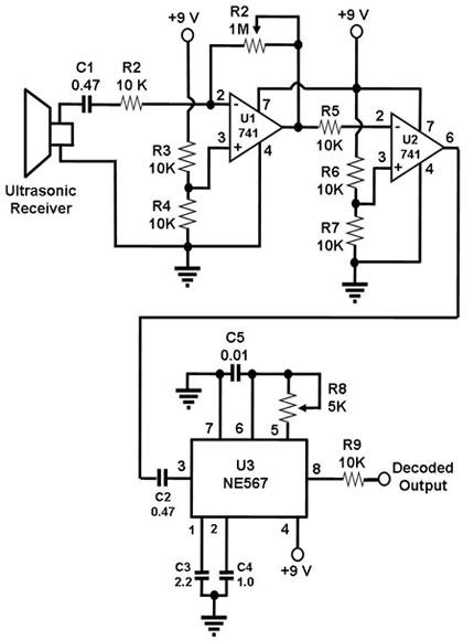
The ultrasonic receiver utilized in this circuit is specifically designed to vibrate optimally at a frequency of approximately 40 kHz. Consequently, the transmitter associated with this receiver must also emit waves at 40 kHz. When these waves interact with...
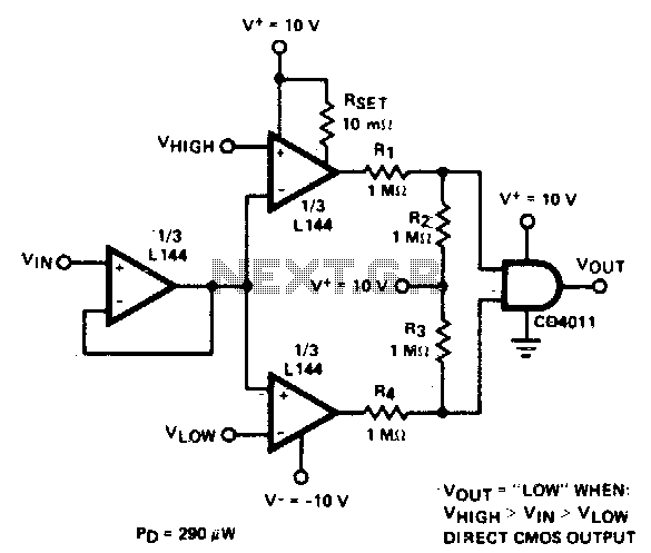
The detector employs three sections of an L144 and a CMOS NAND gate to create a low-power voltage monitor. The 1 MΩ resistors R1, R2, R3, and R4 convert the bipolar ±10 V swing of the operational amplifiers to...
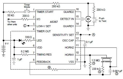
A simple ionization smoke detector with interconnect and timer alarm circuit can be constructed using the A5367 low-current, CMOS circuit, which provides all essential features for an ionization-type smoke detector. This CMOS IC, manufactured by Allegro MicroSystems, includes interconnect...
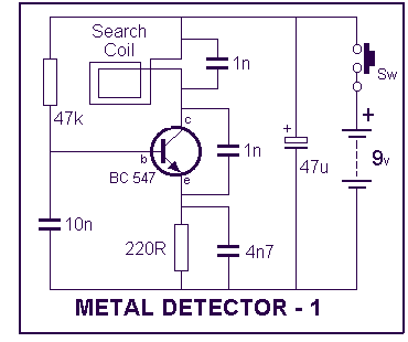
This project has not been called a GOLD detector as this name has been left for the more complex detectors that actually discriminate between gold and other metals. There is an enormous difference between detecting gold and ordinary metals...
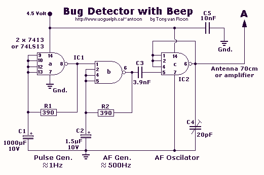
This circuit is not open for discussion. Although working perfectly, it was experimental. I will answer no emails in regards to this circuit. If you are looking for a more serious and reliable bug detector, go to the Countersurveillance...