
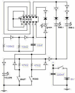
RF Bug detector

The provided text indicates that the circuit in question is experimental and not intended for further discussion or inquiries. As such, it is important to recognize that experimental circuits may not adhere to standard practices or may lack comprehensive documentation. The mention of a "Countersurveillance Monitor" suggests an alternative solution that is deemed more reliable for bug detection purposes.
In general, a bug detector circuit typically employs RF (radio frequency) detection techniques to identify the presence of unauthorized transmitting devices. Such circuits may include components such as RF amplifiers, frequency mixers, and demodulators to process incoming signals. The output can be visualized using an LED indicator or an audio alert to signify the detection of specific frequencies associated with bugging devices.
For those seeking a more robust design, the Countersurveillance Monitor referenced in the text likely incorporates advanced features such as adjustable sensitivity, frequency scanning capabilities, and possibly digital signal processing (DSP) techniques to filter out noise and enhance detection accuracy. This would provide users with a more comprehensive tool for identifying potential surveillance threats in various environments.
In conclusion, while the experimental circuit is acknowledged to function well, it is advisable to refer to established designs or commercially available products for reliable bug detection.This circuit is not open for discussion. Although working perfectly, it was experimental. I will answer no emails in regards to this circuit. If you are looking for a more serious and reliable bug detector, go to the Countersurveillance Monitor article on the Circuits Page. 🔗 External reference
Related Circuits

This schematic diagram illustrates a 555 IC water level sensor and detector alarm circuit. The circuit is powered by the emitter current of the BC109C transistor. The 555 timer operates as an astable oscillator in this configuration. Under dry...
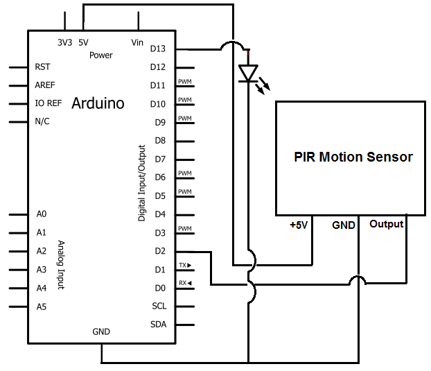
Once the motion sensor detects motion, the Arduino can be programmed to activate an LED, turn on a motor, sound a buzzer, etc. In this circuit, for simplicity, an LED will be turned on when the motion sensor detects...

The 555 timer is configured as a multivibrator in conjunction with an opto-isolator to drive a remote speaker. The circuit utilizes the 555 timer in astable mode to generate a continuous square wave output. This output is then used to...
This circuit is the electronic emulation of the I Ching, a form of divination originating in China. In the classical form, the response is obtained by the manipulation of 50 sticks or, more practically, by tossing 3 coins. The...
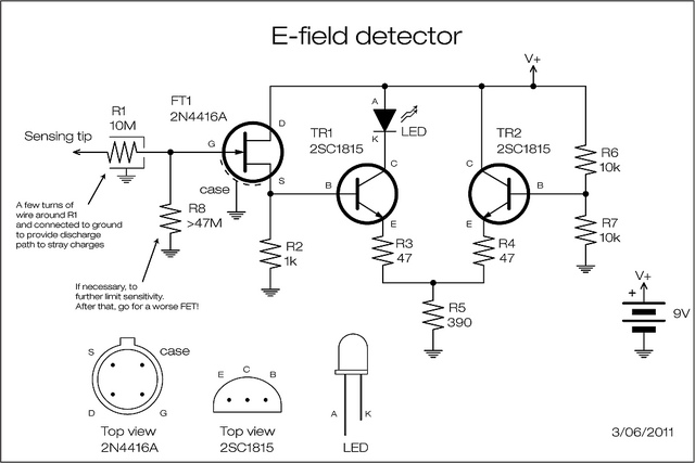
A JFET is employed to detect the electric field generated by high voltage power lines. The JFET amplifies the signal minimally but reduces the impedance and supplies current at a level appropriate for transistor amplification. The two transistors can...
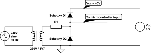
Provide zero crossing detection for the controller. Using the schematic below, a square wave signal was generated, representing the positive and negative half-periods. The issue is that the resistor needs to be quite large, which can lead to excessive...