
ultrasonic receiver circuit
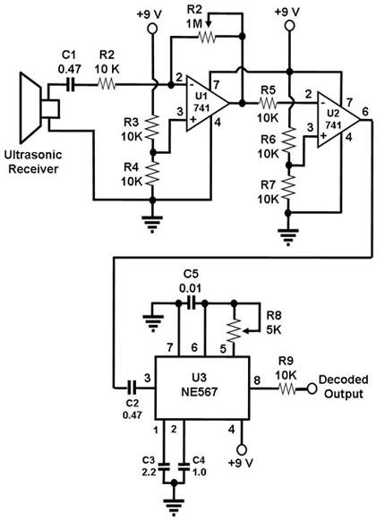
The circuit operates by first generating ultrasonic waves using the transmitter, which is configured to produce a continuous wave at 40 kHz. This wave travels through the environment and reflects off nearby objects. The receiver, tuned to the same frequency, detects these reflections. When the transmitted waves hit an object, they bounce back towards the receiver, causing it to vibrate at 40 kHz. This vibration generates an electrical signal that is weak and requires amplification to be useful.
The two operational amplifiers are configured to increase the strength of the received signal. The first op-amp typically serves as a voltage amplifier, increasing the amplitude of the received signal. The second op-amp may be configured as a filter to eliminate noise and improve the signal-to-noise ratio, ensuring that only the desired frequency is amplified.
The output from the operational amplifiers is then fed into the 567 IC, which is sensitive to the specific frequency of 40 kHz. The PLL within the 567 IC locks onto the incoming signal frequency, and if it matches the set frequency, it produces a high output signal. This output can be used to trigger other components in a system, such as activating an alert or controlling the movement of a robot.
In practical applications, proper placement of the transmitter and receiver is crucial. The receiver should be oriented to receive only the echoes of the ultrasonic waves, which requires careful alignment to avoid direct reception of the transmitted signal. This setup allows for accurate detection of nearby objects, making it an effective solution for obstacle avoidance in robotic systems. The simplicity and effectiveness of this circuit make it a popular choice for various proximity sensing applications.Since the ultrasonic receiver used in this circuit is one designed to vibrate optimally at about 40 kHz, the transmitter paired with this receiver must also transmit 40 kHz waves. When these waves hit the receiver, the receiver vibrates and produces electric impulses, also at 40 kHz.
These electric signals are amplified by the two op amps in the c ircuit, the amplified output of which are fed into the 567 IC. This is a PLL tone decoder, i. e. , it outputs a signal if it detects an input that is tuned to its set frequency (40 kHz in this case). One example of application of this simple receiver (if paired with a matching transmitter, that is) is as a proximity sensor, such as one that can help a robot avoid running into walls.
If used in that manner, the transmitter and receiver transducers must be positioned such that the receiver will only receive echoes of the transmitted signal and not the transmitted signal itself. 🔗 External reference
Related Circuits
The metronome circuit has been assembled multiple times without success. Two manufacturers of the 555 timer, ON Semiconductor and National Semiconductor, provide circuit designs that differ from the original. In their designs, pins 2, 6, and 7 are not...
A varying brightness AC lamp circuit utilizes a silicon-controlled rectifier (SCR) to gradually adjust the intensity of a 120-volt light bulb by controlling the duration of AC line voltage applied to the lamp during each half cycle. The circuit...
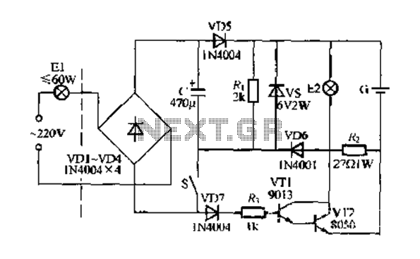
Figure 283 illustrates a blackout emergency lighting controller designed for straightforward external installation with two leads. This controller can directly replace the P Chan Tong Ge opening. Under normal power conditions, it functions like a conventional switch to control...
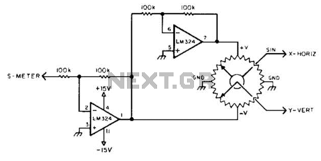
To display polar quantities, which include both the magnitude and direction of a received radio signal, a sine and cosine voltage proportional to an angle corresponding to the antenna direction is required. This setup utilizes a sine-cosine potentiometer connected...
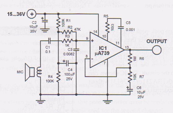
This circuit is a low voltage microphone preamplifier that operates with a 1.5V power supply. It features a reference with a 500 kHz unity-gain bandwidth, functioning as a preamplifier with a gain of 100. The output from this stage...
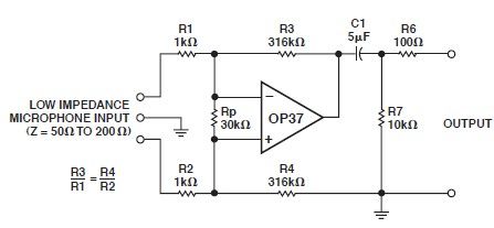
This microphone preamp schematic is an electronic circuit project utilizing the OP37 operational amplifier from Analog Devices. It functions as a fixed-gain transformerless microphone preamp, amplifying differential signals from low-impedance microphones by 50 dB, with an input impedance of...
Warning: include(partials/cookie-banner.php): Failed to open stream: Permission denied in /var/www/html/nextgr/view-circuit.php on line 713
Warning: include(): Failed opening 'partials/cookie-banner.php' for inclusion (include_path='.:/usr/share/php') in /var/www/html/nextgr/view-circuit.php on line 713