
Ultrasonic Parking controller
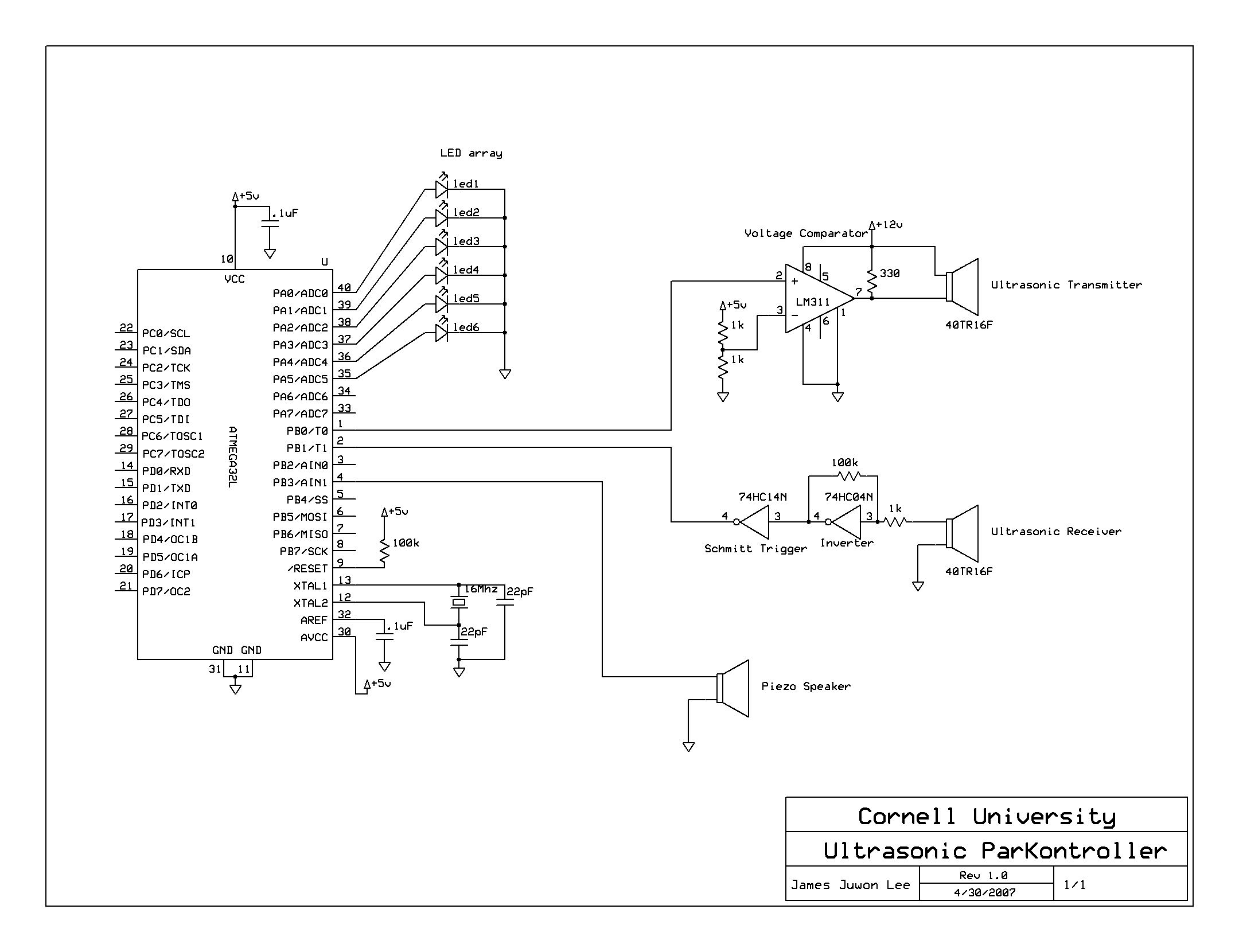
In this circuit design, the microcontroller generates a series of five short pulses with an amplitude of 5V. These pulses are intended for an ultrasonic transducer, but the signal is expected to be significantly attenuated when received, dropping below 20 mV. To ensure that the signal is suitable for driving the transducer, an LM311 voltage comparator is employed. The LM311 is selected for its rapid switching capabilities, with a low-to-high response time of 115 ns and a high-to-low response time of 165 ns, both of which are adequate given that each pulse has a width of 12.5 µs.
The LM311 compares the incoming 5V pulse against a reference voltage of 2.5V. If the input pulse exceeds this threshold, the comparator outputs a 12V signal, which is drawn from the power supply to activate the ultrasonic transducer. If the input pulse does not exceed 2.5V, the output is zero. This amplification results in 5V input pulses being transformed into 12V output pulses, which are necessary for the transducer to emit sound waves at a frequency of 40 kHz.
Upon receiving the ultrasonic sound waves, the transducer generates a corresponding voltage signal, which is initially around 50 mV. To convert this low voltage signal into a usable 5V signal, a 74HC04N Hex Inverter is utilized in conjunction with a resistor network consisting of a 100 kΩ resistor and a 1 kΩ resistor, providing a gain of 100. The inverter's propagation delay is minimal at 19 ns, ensuring that the switching speed remains efficient.
The amplified and inverted signal from the inverter is then processed by a 74HC14N Schmitt Trigger. This component is essential for producing a clean square wave output. The Schmitt Trigger has a threshold voltage of 2.5V; any input signal below this level results in a logical low output (0V), while inputs above this threshold yield a logical high output (5V). The inverted signal from the inverter is restored to its original polarity by the Schmitt Trigger, and the resulting output is sent to port B.1 of the microcontroller for further processing and distance calculation. This systematic approach ensures reliable signal transmission and accurate distance measurement in ultrasonic applications.A series of five short pulses blasted by the microcontroller only has 5V amplitude, which will be attenuated down to less than 20 mV when received by the receiver circuit. Hence, LM311 voltage comparator was used for signal amplification before transmitting the signal. LM311 was used instead of regular operational amplifier since it has faster switching speed. Low-to-high and high-to-low level output response times were only 115ns and 165ns respectively, which was more than enough for our application since the width of each pulse is 12.5us.
The voltage comparator compares the 5V input pulse generated by the MCU to 2.5V. If the voltage level of the input pulse is greater than 2.5V it outputs 12V drawn from the power supply and drives the ultrasonic transducer, otherwise it outputs zero. Hence the 5V input pulses are amplified to 12V pulses. The ultrasonic transducer converts its input voltage into sound waves and emits them at 40kHz frequency.
First, the ultrasonic transducer converts the received sound wave into voltage. The received signal was only about 50mV, which means that it has to be amplified by a factor of 100 to get a 5V signal. Hence, 74HC04N Hex Inverter with 100kW/1kW resistor pair was used to achieve a gain of 100. The propagation delay of the inverter was only 19ns, so switching speed was not of our concern. The inverted and amplified signal was then inputted to a 74HC14N Schmitt Trigger to produce a clean square wave.
Any value below the trigger voltage (2.5V) gave logical zero (0V) and any value above 2.5V gave logical high (5V). Note that the inverted signal from the inverter is inverted back by the Schmitt trigger. The output of the Schmitt trigger is then fed into port B.1 for microcontroller processing and distance calculation.
🔗 External reference
Related Circuits
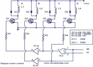
The following circuit illustrates a Stepper Motor Controller Circuit Diagram. This circuit is based on the 7404 IC. Features include a simple stepper motor. The stepper motor controller circuit utilizing the 7404 IC is designed to drive a stepper motor...
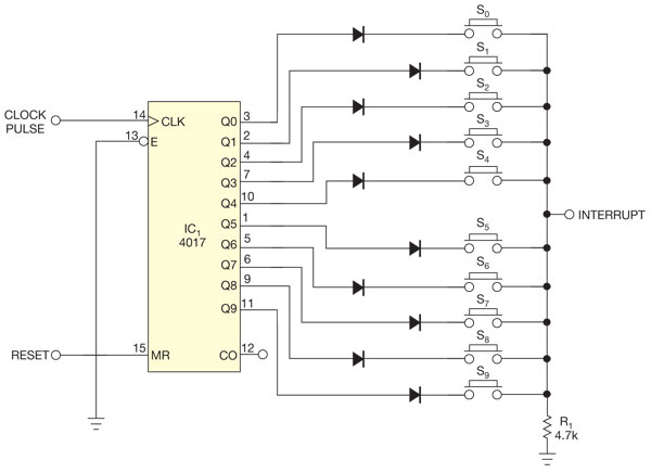
There are several methods to read multiple switch inputs using a reduced number of microcontroller unit (MCU) pins. One approach involves using an analog MCU pin to read multiple switches by assigning a unique voltage to each switch through...
This Project is used to control a single phase Motor from any where in the world through the telephone. The circuit consists of a DTMF tone detector and a powerful 8 bit Microcontroller AT89S52. The Microcontroller senses the DTMF...
The Controller Area Network (CAN) data rate ranges from 10 kbit/s to 1 Mbit/s, with recommended distances of 40 to 1000 meters using two twisted pairs—one for data and the other for power and ground. Up to 110 nodes...
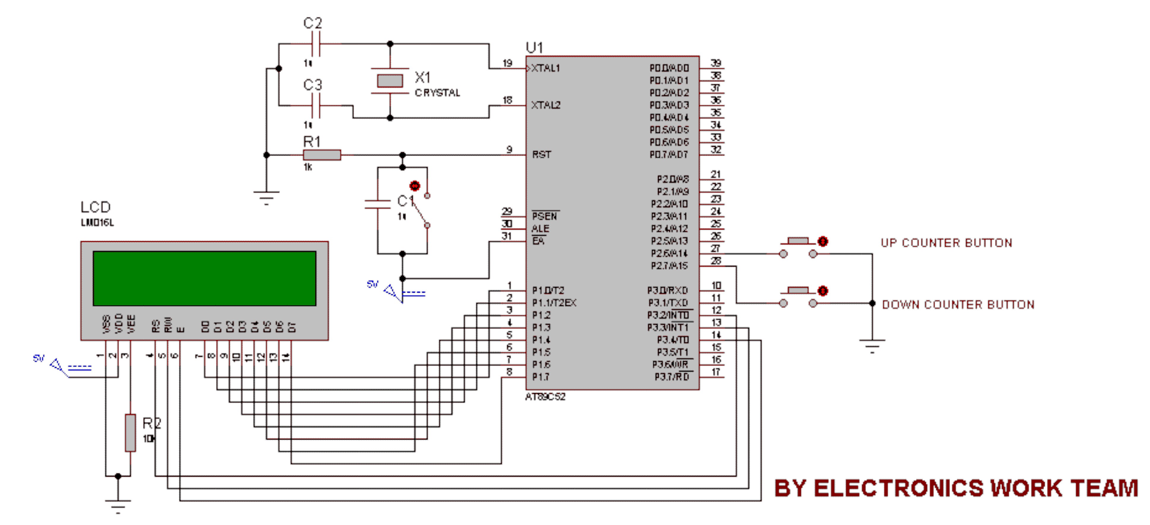
This circuit utilizes a 16x2 LCD to display a count value using an 8051 microcontroller. The maximum count value is set to 99. The circuit consists of the 8051 microcontroller, a 16x2 LCD, and two switches designated for incrementing...
Microdot - wrist watch LED pattern timepiece. This project is a circuit board designed for creating a wristwatch-sized version. The Microdot wristwatch project involves the design and implementation of a compact circuit board that integrates LED technology to display time...