
555 IC For Basic Monostable Multivibrator

The basic monostable multivibrator circuit using the 555 Timer IC operates by producing a single output pulse in response to a triggering input. When the trigger pin (pin 2) receives a negative pulse, the output (pin 3) goes high for a duration determined by the resistor (R1) and capacitor (C1) values. The time period of the output pulse can be calculated using the formula t = 1.1 x R1 x C1, where t is the pulse width in seconds, R1 is in ohms, and C1 is in farads.
In this configuration, pin 4 serves as the RESET pin, allowing the circuit to be reset and the output pulse to be terminated prematurely if needed. The 555 Timer can be powered by a standard DC supply, typically between 5V and 15V, depending on the specific requirements of the application.
The circuit typically includes a diode connected in parallel with the timing capacitor to discharge it quickly when the output goes low, ensuring reliable operation. The design can be adapted for various applications, such as timers, pulse generators, or frequency dividers, by adjusting the values of R1 and C1.
In practical applications, it is essential to consider the tolerance of the resistor and capacitor, as variations can significantly affect the timing accuracy. Additionally, bypass capacitors may be included near the power supply pins to filter out noise and ensure stable operation of the 555 Timer IC.Description:The following circuit shows about Basic Monostable Multivibrator. This circuit based on the 555 Timer IC. Features: Pin 4 is the RESET, t=R1xC1, .. 🔗 External reference
Related Circuits
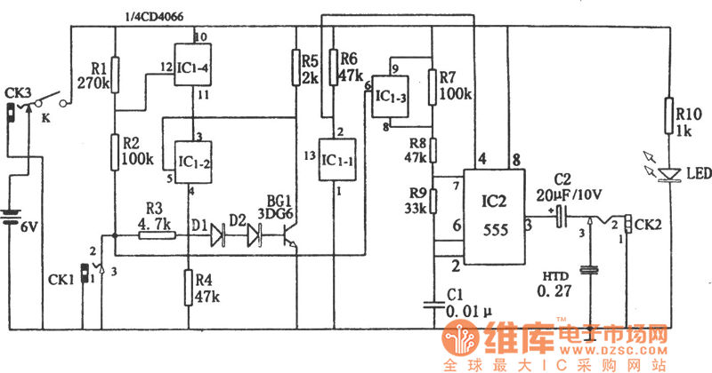
The circuit diagram illustrates a five-use tri-state audio logic pen utilizing components such as the CD4066 and a 555 timer. The primary elements include a multivibrator, a four-way switch (CD4066, designated as IC1), and a gate circuit formed by...

The pulse-width detection circuit is illustrated in the figure and consists of a differential circuit (R2, C2), an amplifier (BG1), a single stabilizing circuit (555, R1, C1), and various other components. The pulse signal Vin (depicted as waveform A)...
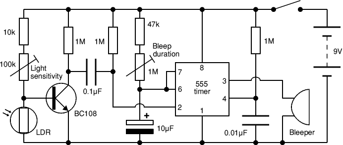
The function of this circuit is to detect a sudden shadow falling on the light sensor and to activate a buzzer when this occurs. The light sensor is designed to monitor ambient light levels. The circuit utilizes a light-dependent resistor...
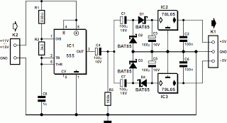
The circuit presented here can convert a single-ended supply voltage into a balanced set of supply voltages. This is achieved without the use of difficult-to-obtain, exotic integrated circuits. All components utilized in the circuit are common and likely available...

Most switch-mode power supplies utilize a PWM (pulse-width-modulated) output that is regulated through voltage feedback. A 555-timer IC can be used to generate PWM at a low cost. The circuit diagram illustrates how to convert a 555 PWM circuit...

This project involves controlling an AVR microcontroller (MCU) using Visual Basic 6. The applications of this circuit are numerous, enabling the creation of various devices that require control from a Personal Computer (PC) or any circuit that collects data...
Warning: include(partials/cookie-banner.php): Failed to open stream: Permission denied in /var/www/html/nextgr/view-circuit.php on line 713
Warning: include(): Failed opening 'partials/cookie-banner.php' for inclusion (include_path='.:/usr/share/php') in /var/www/html/nextgr/view-circuit.php on line 713