
ultrasonic switch circuit
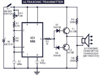
The circuit operates by generating ultrasonic sound waves, which are transmitted over a short distance. The 555 timer in astable mode provides a continuous square wave output, driving the ultrasonic transducer to emit sound. The frequency range of 40-50 kHz is chosen as it is above the human hearing threshold, allowing for silent operation while still being detectable by the receiver.
The ultrasonic receiver circuit is designed to be sensitive to the specific frequency emitted by the transmitter. The receiver transducer converts incoming ultrasonic waves into electrical signals, which are then amplified through a two-stage transistor amplifier (T3 and T4). This amplification is crucial for ensuring that the signals are strong enough to be processed by the subsequent rectifier and operational amplifier stages.
The rectifier stage converts the AC signals from the receiver transducer into DC voltage, which is then filtered to smooth out any fluctuations. The filtered voltage is applied to the inverting input of the operational amplifier (IC2). By adjusting the preset resistor (VR2), the sensitivity of the receiver can be fine-tuned, allowing for reliable operation in various environmental conditions.
The relay driver stage is designed to handle the output from the op-amp, providing sufficient current to energize the relay (RL1). This relay can be used to control various loads, such as lights or motors, depending on the application. The use of a DPDT relay allows for versatile switching options, enabling both ON and OFF control of the connected load.
Care should be taken to ensure proper alignment between the transmitter and receiver transducers, as ultrasonic signals are highly directional. Misalignment can lead to reduced sensitivity and potential failure to activate the relay. Additionally, the potential for false triggering due to ambient ultrasonic noise should be considered, especially in environments where other ultrasonic sources are present.The circuit described generates (transmits) ultrasonic sound of frequency between 40 and 50 kHz. As with any other remote control system this cirucit comprises of a mini transmitter and a receiver circuit. Transmitter generates ultrasonic sound and the receiver senses ultrasonic sound from the transmitter and switches on a relay.
The ultrasonic tr ansmitter uses a 555 based astable multivibrator. It oscillates at a frequency of 40-50 kHz. An ultrasonic transmitter transducer is used here to transmit ultrasonic sound very effectively. The transmitter is powered from a 9-volt PP3 single cell. The ultrasonic receiver circuit uses an ultrasonic receiver transducer to sense ultrasonic signals. It also uses a two-stage amplifier, a rectifier stage, and an operational amplifier in inverting mode. Output of op-amp is connected to a relay through a complimentary relay driver stage. A 9-volt battery eliminator can be used for receiver circuit, if required. When switch S1 of transmitter is pressed, it generates ultrasonic sound. The sound is received by ultrasonic receiver transducer. It converts it to electrical variations of the same frequency. These signals are amplified by transistors T3 and T4. The amplified signals are then rectified and filtered. The filtered DC voltage is given to inverting pin of op-amp IC2. The non- inverting pin of IC2 is connected to a variable DC voltage via preset VR2 which determines the threshold value of ultrasonic signal received by receiver for operation of relay RL1.
The inverted output of IC2 is used to bias transistor T5. When transistor T5 conducts, it supplies base bias to transistor T6. When transistor T6 conducts, it actuates the relay. The relay can be used to control any electrical or electronic equipment. 2. Ultrasonic sounds are highly directional. So when you are operating the switch the ultrasonic transmitter transducer of transmitter should be placed towards ultrasonic receiver transducer of receiver circuit for proper functioning. 4. For latch facility use a DPDT relay if you want to switch on and switch off the load. A flip-flop can be inserted between IC2 and relay. If you want only an ON-time delay` use a 555 only at output of IC2. The relay will be energised for the required period determined by the timing components of 555 monostable multivibrator.
5. Ultrasonic waves are emitted by many natural sources. Therefore, sometimes, the circuit might get falsely triggered, espically when a flip-flop is used with the circuit, and there is no remedy for that. 🔗 External reference
Related Circuits
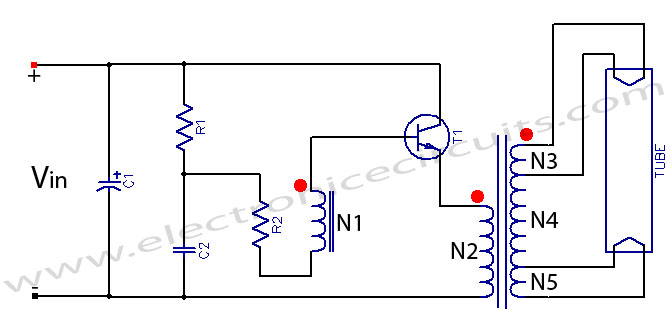
Fluorescent tube light circuit of an inverter that uses a single transistor and a single transformer. This type of inverter can be made in various configurations. The fluorescent tube light circuit described utilizes a basic inverter design that incorporates a...
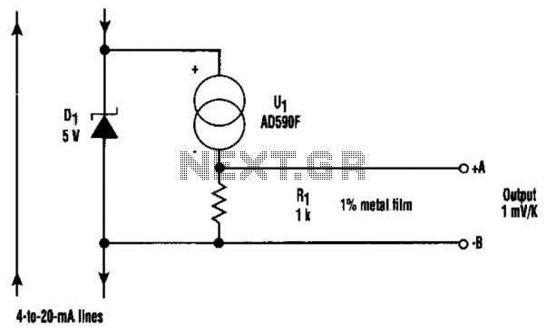
This circuit is designed for precise measurement of temperature in degrees Celsius. It features a transmitter section that converts the output voltage from the temperature sensor, which is proportional to the measured temperature, into a frequency signal. This frequency...

The circuit for the RS232 serial interface exhibits mild complexity. The primary components of the circuit include the 18F4520 microcontroller, MAX233A level shifter, and a DB-9 connector. This circuit utilizes a basic +5V power regulator to supply the digital...
DCF77 Preamplifier Circuit Diagram A popular project among microcontroller enthusiasts is to build a radio-controlled clock. Small receiver boards are available, equipped with a pre-adjusted ferrite antenna, that receive and demodulate the DCF77 time signal broadcast from Mainflingen in...
At the core of this circuit is the KTY10 temperature sensor from Siemens. This silicon sensor functions as a temperature-dependent resistor, integrated as one arm of a bridge circuit. A preset potentiometer (P1) is used to balance the bridge...
The circuit of a loop sensor-based simple security alarm is described here. The sensor loop consists of a short length of thin enamelled copper wire. The loop sensor security alarm operates on the principle of detecting interruptions in the circuit...