
AM Transmitter
The AM transmitter circuit is designed to modulate audio signals onto a carrier wave for transmission. The audio amplifier section processes the input audio signal, enhancing its amplitude to a level suitable for modulation. Typically, this section may include operational amplifiers or transistor-based amplifiers to achieve the desired gain.
The RF oscillator generates the carrier frequency, which is crucial for AM transmission. It operates using Q1, which is likely a transistor or a field-effect transistor (FET), along with passive components such as resistors and capacitors. The oscillator's frequency is determined by the tank circuit formed by inductor L1 and variable capacitor VC1. The tunable nature of VC1 allows the user to adjust the frequency, enabling operation across a range from 500 kHz to 1600 kHz, which is suitable for AM broadcasting.
In this schematic, the output of the RF oscillator can be connected to an antenna for transmission. The design must consider impedance matching to ensure efficient power transfer to the antenna. Additionally, filtering components may be included to suppress harmonics and ensure that the transmitted signal meets regulatory standards for spectral purity.
Overall, this AM transmitter schematic diagram illustrates a fundamental approach to building a basic AM transmitter, suitable for educational purposes or hobbyist projects. Proper attention to component selection, layout, and tuning will enhance the performance and reliability of the transmitter.This is AM transmitter schematic diagram. The circuit is in two halfs, an audio amplifier and an RF oscillator. The oscillator is built around Q1 and associated components. The tank circuit L1 and VC1 is tunable from about 500kHz to 1600KHz.. 🔗 External reference
Related Circuits
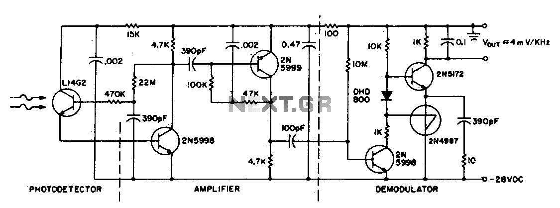
This circuit consists of an L14G2 detector, two stages of gain, and an FM demodulator. Better sensitivity can be obtained using more stages of stabilized gain with automatic gain control (AGC). The circuit design features an L14G2 detector, which serves...
This transmitter is highly stable and can deliver up to seven watts of power using the specified components and tubes. The use of valves should not deter users, as they are straightforward to work with, and many valves can...
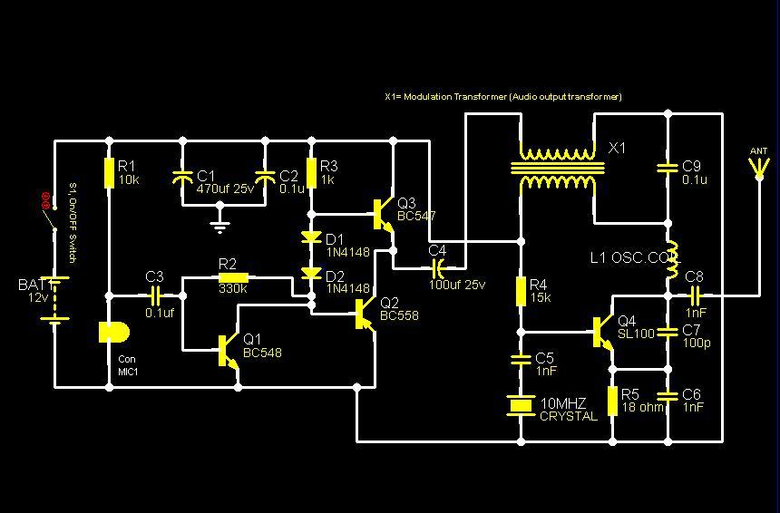
The core component of this circuit is a crystal oscillator utilizing a 10MHz crystal to generate a highly stable carrier frequency. The sound signal from a condenser microphone is amplified by an amplifier circuit comprised of transistors Q1, Q2,...
The operation of the 6CL6 transmitter is quite sophisticated despite the simple appearance of the circuit. The core of the circuit is the electron-coupled crystal oscillator. This circuit integrates the functions of an oscillator and amplifier into a single...
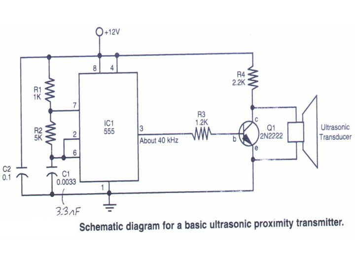
This section provides step-by-step instructions along with images for constructing an Ultrasonic Proximity Transmitter. Due to the simplicity of the circuit, only a schematic for the sensor is presented here. The objective of this tutorial is to assist others...
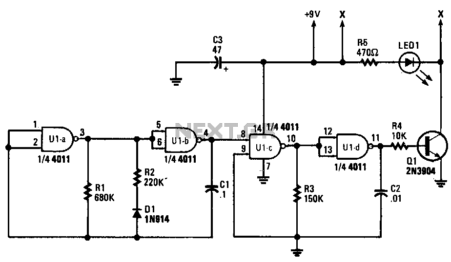
Gates U1a and U1b are configured as a low-frequency oscillator. The output waveform at pin 11 is nonsymmetrical, with the positive portion of the signal comprising only 20% of the time period. Diode D1, a 1N914 general-purpose unit, along...