
1000 watt power inverter circuit diagram
The circuit design utilizes the RF50N06 MOSFET, which is a N-channel MOSFET capable of handling significant current and voltage, making it suitable for high-power applications such as inverters. The inverter operates by converting DC voltage into AC voltage, which is essential for powering household appliances or other devices that require alternating current.
To construct the inverter, the following components are necessary: the RF50N06 MOSFETs, a suitable output transformer, a fuse for protection, and additional passive components such as resistors and capacitors for stability and filtering. The transformer plays a critical role in determining the output voltage and current, and selecting an appropriate transformer is crucial for achieving the desired output power.
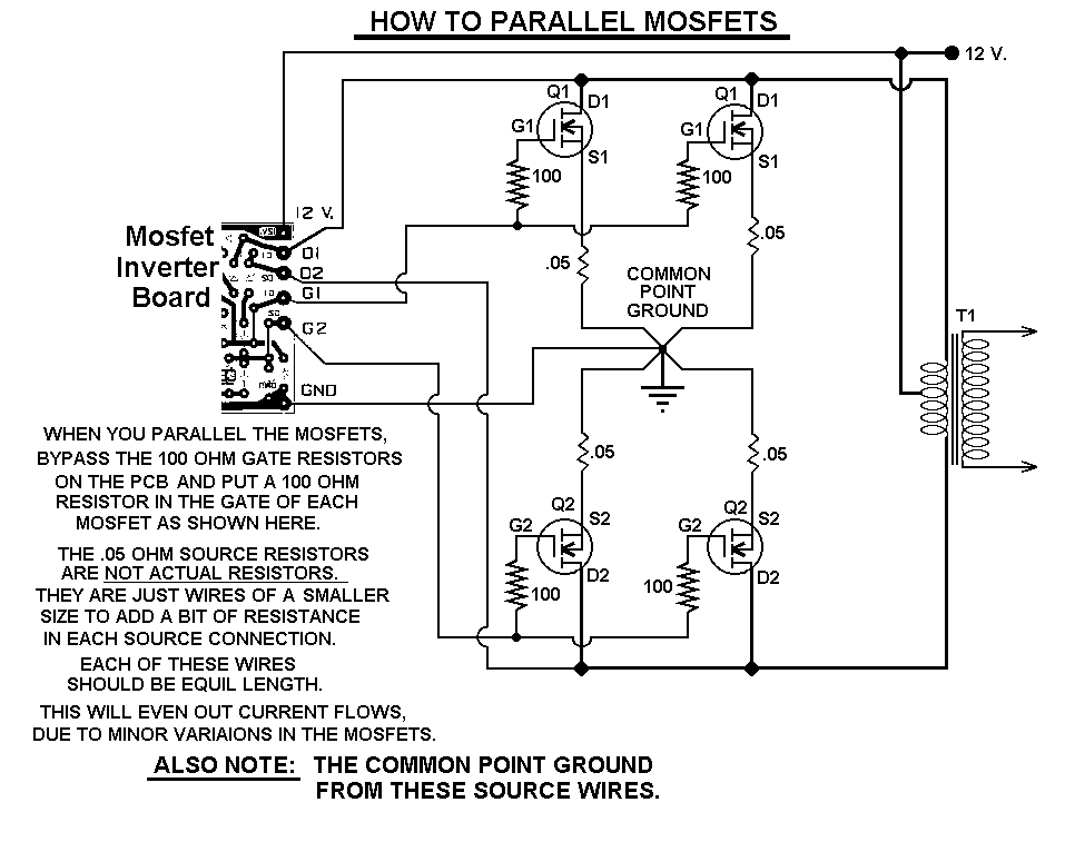
When paralleling MOSFETs, it is important to ensure that they are matched in characteristics to avoid unequal current sharing, which can lead to overheating and failure. Gate resistors may be added to each MOSFET to help balance the switching times and improve reliability.
The fuse serves as a safety feature, protecting the circuit from overcurrent conditions that could damage the components or pose a fire hazard. Proper sizing of the fuse is essential to ensure it operates within the safe limits of the circuit.
The inverter should be tested under controlled conditions, gradually increasing the load to monitor performance and ensure stability. Experimentation with different transformer designs and configurations can lead to improvements in efficiency and output quality.This 1000 watt power inverter circuit diagram based on MOSFET RF50N06. If you want more power then add additional MOSFET paralleled at RF50N06. This MOSFETS are 60 Volts and 50 Amps as rated. It is necessary to connect a FUSE with the power line and always a LOAD have to connected while power is being applied. The output power of this inverter is u p-to 1k watt, it depends on output power transformer. You can use your custom transformer with experimenting for best result. 🔗 External reference
Related Circuits
This AC to DC power supply can output 5A in continuous operation and 12A peak current. This type of DC power supply uses a PCB, allowing for two case types for IC1: TO-220 or TO-3. The regulation of this...
If 40 watts RMS from 20Hz to 30KHz +/-1.5 dB is appealing, this experiment may be of interest. A significant issue with public address equipment is the use of audio output transformers that lack sufficient iron to manage lower...
Radio-frequency schematics (also see NE602 datasheet and application note). This page contains electronic circuits related to RF receivers. This index features a broad collection of RF receiver circuits. Radio-frequency (RF) schematics are essential for designing and implementing circuits that operate...
Construct a low-power FM transmitter using surface-mount devices (SMD) that can be received by a standard FM radio. The proposed low-power FM transmitter circuit utilizes surface-mount devices (SMD) to achieve compactness and efficiency. The primary components of the circuit include...
This circuit will supply up to approximately 20 mA at 12 volts. It utilizes capacitive reactance instead of resistance and does not generate significant heat. The described circuit operates as a capacitive power supply, which is an efficient method to...
A circuit is being designed to operate based on car locks, which receive a negative pulse to activate a latched relay, powering the ACC line that connects to a startup/shutdown controller. The current circuit configuration presents a challenge; to...
Warning: include(partials/cookie-banner.php): Failed to open stream: Permission denied in /var/www/html/nextgr/view-circuit.php on line 713
Warning: include(): Failed opening 'partials/cookie-banner.php' for inclusion (include_path='.:/usr/share/php') in /var/www/html/nextgr/view-circuit.php on line 713