
Unipolar Stepper Motor Control Circuit
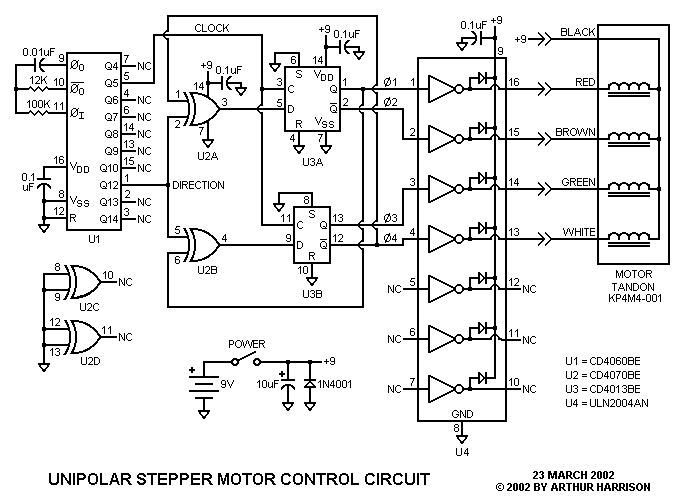
The circuit design is structured around a unipolar stepper motor, specifically the KP4M4-001 model. This motor operates through a four-phase system, which allows for precise control of its rotational position. The primary components include a relaxation oscillator and a binary ripple counter integrated within U1, which generates the necessary clock signals for the flip-flops. The Q5 output from U1 is critical as it produces a 100 Hertz signal, effectively driving the motor's step transitions.
The use of "D" flip-flops U3A and U3B is essential for maintaining the state of the motor control signals. These flip-flops receive the clock signal from U1 and output the necessary control signals that determine the direction and stepping of the motor. The complementary outputs generated by the exclusive-or gates U2A and U2B create the quadrature waveforms that are pivotal for the motor's operation. This configuration allows for smooth and controlled stepping of the motor, providing a reliable method for positioning applications such as in radar systems.
The Darlington drivers in U4 serve as the interface between the control signals and the motor, supplying the necessary current to drive the motor coils. This is crucial, as stepper motors require significant current to achieve the desired torque and speed. The relationship between the clock frequency and motor speed is also notable; increasing the clock frequency results in faster motor rotation, up to the limits defined by the motor's mechanical characteristics and load conditions.
The circuit is designed to be versatile, operating effectively within a voltage range of 6 to 12 volts. This flexibility allows for adjustments based on specific application requirements, including load torque and desired speed. The recommendation for a power supply over batteries for continuous operation underscores the current demands of the motor, which can draw up to 160 milliamperes at 9 volts. Overall, this circuit exemplifies a practical application of stepper motor technology in electronic control systems, providing a reliable solution for precise movement in various engineering and hobbyist projects.This circuit controls a small, four-phase, five-wire, unipolar stepper motor, commonly designated the "KP4M4-001. " This type of motor was used in many 5 1/4" floppy disk drives in older computers. Now obsolete, such disk drives are often available on the surplus market for a small fraction of the motor`s original cost.
The stepper motors are easy to extract from the drives, and are ideal for many applications. This arrangement was used in the scale model of a RADAR set to control the position of a miniature parabolic antenna. (Note that some 5 1/4" floppy disk drives used a four-wire "bipolar" motor, which is not compatible with this circuit.
) Referring to the schematic, U1 contains a relaxation oscillator and a binary ripple counter. U1`s Q5 output provides a 100 Hertz square wave for the clock inputs of "D" flip-flops U3A and U3B. U1`s Q12 output provides a level that alternates between "low" and "high" logic levels every 64 cycles of Q5. This signal is applied to the inputs of exclusive-or gates U2A and U2B. The flip-flops and gates form a quadrature waveform generator with complimentary outputs. These waveforms are applied to U4, a set of Darlington drivers capable of providing the required sink current for the motor.
The waveforms and their relationships are illustrated in the following figure. The motor rotates one step, or 3. 6 degrees, for each positive clock transition. Rotation occurs in one direction for 230. 4 degrees (64 clock cycles x 3. 6 degrees), and then reverses. Clockwise rotation occurs when U1`s Q12 output is a logic "high" level, and counterclockwise rotation occurs when it is "low. " If desired, pins 2 and 5 of gates U2A and U2B may be disconnected from the counter, and alternatively provided with an external direction control signal.
The 12K timing resistor may be substituted with other values, with greater resistance decreasing the motor`s speed. The maximum speed is determined by the motor`s mechanical characteristics and load torque. For the prototype, operating at 9 volts, the clock frequency could be increased to 250 Hertz, while still providing smooth operation.
The circuit uses about 160 milliamperes at 9 volts, with a majority of the current consumed by the motor. Therefore, a power supply is recommended in lieu of a battery if continuous operation is desired. The circuit will operate from 6 to 12 volts, depending on load torque and speed. 🔗 External reference
Related Circuits
The following circuit illustrates a Lie Detector Circuit Diagram. Features include a capacitor that eliminates the 50Hz induced mains hum present in the circuit. The Lie Detector Circuit operates on the principle of measuring physiological responses, typically galvanic skin response...
Do not like your little brother's TV channel selection? Hate the volume your wife sets the stereo at? Want to just annoy someone? This circuit accomplishes all of that and more by jamming most infrared (IR) remote signals. The...
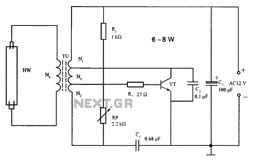
The lighting inverter circuit is designed for 6 to 8W fluorescent tubes. This circuit is appropriate for powering fluorescent tube circuits within the specified wattage. The parameters for the circuit are indicated in the accompanying figure. When utilizing a...
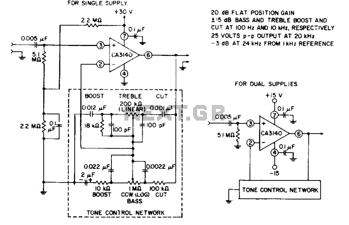
The circuit effectively utilizes the high slew rate, wide bandwidth, high input impedance, and high output voltage capability of the CA3140 BiMOS operational amplifier. The wideband gain of this circuit is equal to the ultimate boost or cut plus...
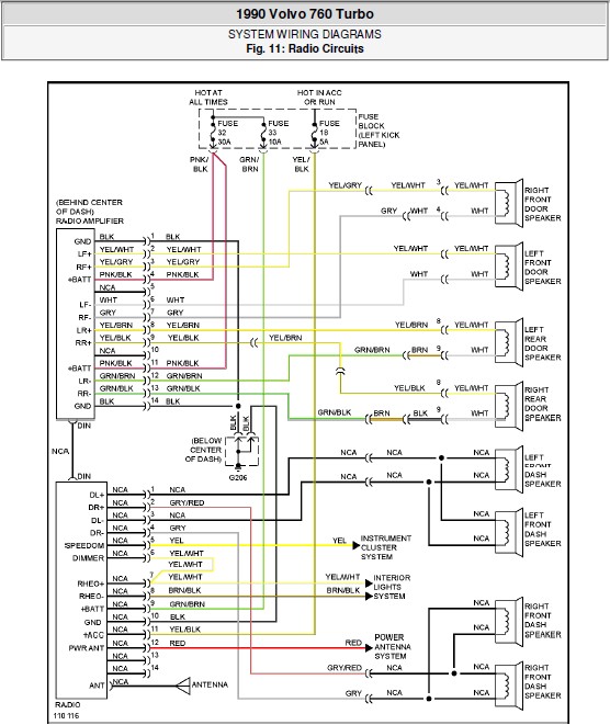
The following document contains the system wiring diagram of the radio circuit for the Volvo 760 Turbo 1990. Please note that this is a system wiring diagram, not a schematic diagram. Download the radio circuit system wiring for the...
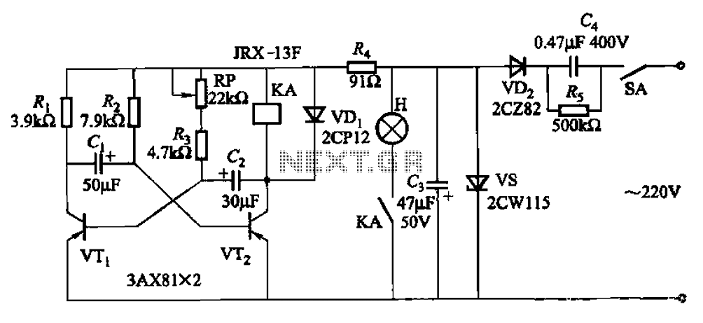
The circuit features a self-excited multivibrator composed of transistors VTi and VTZ. It includes an adjustment potentiometer RP and two RC networks that influence the transistors' parameters, specifically the timing for light activation and deactivation. The described multivibrator circuit utilizes...