
Bass and Tremble Controller ( 741 )
The circuit described utilizes the LM741 operational amplifier, configured to create a tone control system that enhances audio signals by adjusting bass and treble frequencies. The design includes two T-filters, which are integral for modifying the audio response. The potentiometers P1 and P2, both rated at 100 kOhm, serve as user controls for bass and treble adjustments, respectively.
When P1 is adjusted, it alters the feedback network involving resistor R1 (10 kOhm), effectively increasing the bass response of the audio signal. Conversely, adjusting P2 modifies the treble response by interacting with capacitor C6 (3.3 nF), allowing for fine-tuning of higher frequency sounds. The circuit is designed to be compatible with various amplifiers, making it versatile for different audio applications.
The power supply requirements for the circuit range from 9 to 12 volts, with a current consumption of several milliamperes, ensuring that it can operate efficiently without significant power draw. The component selection includes resistors (R1, R2, R3, R5, R6 at 10 kOhm and R4 at 4.7 kOhm) and capacitors (C1 at 100 µF/16V, C2 and C8 at 4.7 µF/16V, C3 and C4 at 33 nF, C5 and C6 at 3.3 nF, and C7 at 22 µF/16V), which are crucial for establishing the desired frequency response characteristics.
For applications where audio fidelity is critical, it is noted that replacing the LM741 with a TL081 op-amp may yield improved audio quality, as the TL081 is known for its lower noise and higher bandwidth specifications.
Overall, the circuit is designed for ease of integration into existing audio systems, with careful attention to component values and layout considerations for PCB design to ensure optimal performance and reliability.Again, using the versatile IC 741. The feedback of this IC are two T-filters included the strengthening of the treble and bass influence. P1 is responsible for regulating the bass and treble controls P2. Where P1 to the direction of R1 is rotated, the enhanced bass. The circuit boosts the treble when P2 is turned to C6. This should be designing the PCB to be taken into account (normally, the right turn of a potentiometer eenversterking result).
This tone control can be switched to different amplifiers. The power supply voltage should be between 9 and 12 volts down, the current consumption is several mA. If one is concerned about the audio quality of this 741 without modification to replace a TL081. Parts List R1, R2, R3, R5, R6 = 10 kOhm R4 = 4.7 kOhm P1, P2 = 100 kOhm linear C1 = 100 V ?F/16 C2, C8 = 4.7 V ?F/16 C3, C4 = 33 nF C5, C6 = 3.3 nF C7 = 22 V ?F/16 IC1 = LM 741 🔗 External reference
Related Circuits
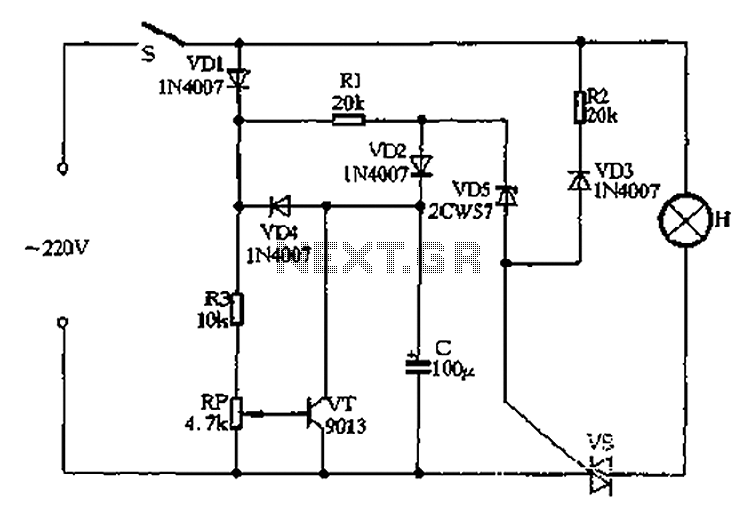
Closing switch S allows the power supply's positive half cycle to flow through VD1, R1, and VD2 to charge capacitor C. The voltage across capacitor C gradually increases but remains significantly lower than the threshold voltage of the zener...
This moisture detector with pump controller is built around the special purpose LM1830 IC. The LM1830 is designed to detect moisture by passing an AC current through a set of probes. An internal comparator compares the resistance of the...
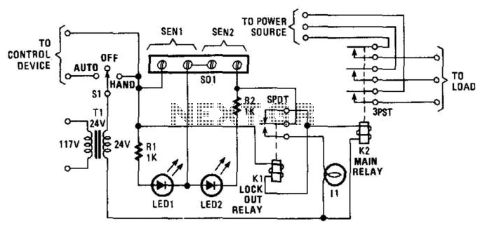
Relay K1 features a low-impedance coil, while Relay K2 is equipped with a high-impedance coil. When a sensor opens, current flows through the coil of K1, activating it. This action opens the contacts of K1, thereby preventing the reclosure...
The following circuit illustrates a simple stepper motor controller circuit diagram. This circuit is based on the 7404 integrated circuit. Features include suitable heat dissipation. The simple stepper motor controller circuit utilizes the 7404 hex inverter IC to control the...
At half brightness, the lamp current is pulsed on and off by the voltage developed across the resistor and capacitor at the current-sense output. The current-sense output detects the lamp current. A basic pulse-width modulation (PWM) lamp-brightness control circuit...
Neural networks are a broad topic. This example demonstrates how to create a basic neural sensor that takes resistive readings from multiple sensors, multiplies them by a weight factor, and then sums the results. The results are compared to...