
universal battery charger schematic
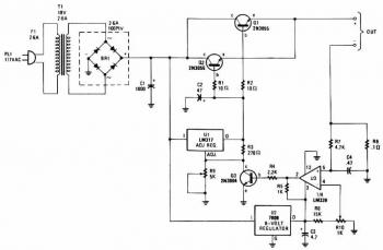
The described charger circuit operates effectively for charging a variety of battery types, including both single cells and series-connected configurations, ensuring flexibility in application. The use of power transistors Q1 and Q2 in a series regulator arrangement allows for efficient control over the output voltage and current, which is crucial for maintaining battery health and optimizing charging efficiency.
The LM-317 adjustable voltage regulator plays a pivotal role in providing a stable drive signal to the power transistors, allowing for fine-tuning of the output voltage. The incorporation of potentiometer R9 facilitates user adjustments to the output voltage level, accommodating different battery specifications.
The current sensing mechanism implemented with resistor R8 is vital for monitoring the charging current. By generating a 100mV signal for each ampere of current, it enables accurate feedback to the comparator U3, which is essential for maintaining the desired charging conditions. The arrangement of the comparator with variable resistor R10 allows for additional customization, ensuring that the circuit can adapt to various charging scenarios.
The feedback loop involving comparator U3 and transistor Q3 is a critical feature of this charger design. As the battery voltage drops, the charging current decreases, leading to a proportional response in the control circuit. This dynamic regulation process ensures that the battery is charged safely and efficiently, preventing overcharging and extending the battery's lifespan.
Overall, this charger circuit exemplifies a robust design that integrates essential components for effective battery management, providing a reliable solution for charging applications in various electronic systems.The charger can charge a single cell or a number of series-connected cells up to a maximum of 18V. Power transistors Q1 and Q2 are connected as series regulators to control the battery charger`s output voltage and charge-current rate. An LM-317 adjustable voltage regulator supplies the drive signal to the bases of power transistor Q1 and Q2.
Potensiometer R9 sets the output-voltage level. A current sampling resistor, R8 (a 0. 1 ohm/5W unit), is connected between the negative output lead and circuit ground. For each amp of charging current that flows through R8, a 100mV output is developed across it. The voltage developed across R8 is fed to one input of comparator U3. The other input of the comparator is connected to variable resistor R10. As the charging voltage across the battery begins to drop, the current through R8 decrease. Then the voltage feeding pin 5 of U3 decreases, and the comparator output follows, turning Q3 back off, which completes the signal`s circular path to regulate the battery`s charging current. 🔗 External reference
Related Circuits
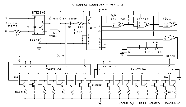
This circuit was designed to control a 32 channel Christmas light show from the PC serial port. Originally designed with TTL logic, it has been simplified using CMOS circuits to reduce component count. It is a fairly simple, reliable...
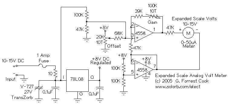
This circuit is used to measure the voltage on a 12V (nominal) lead acid rechargeable battery system. It was specifically designed for use in solar powered systems, but is general enough that it can be used for automotive or...
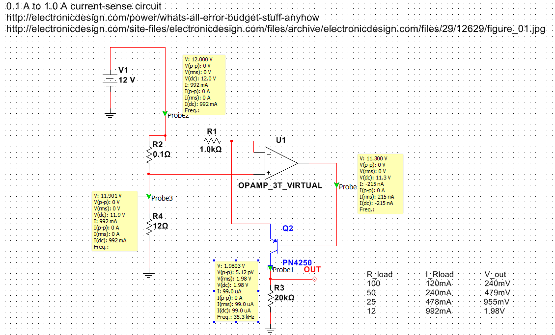
Exploring various methods for current sensing using standard operational amplifiers instead of specialized chips like the MAX4073T/F/H, which perform well but are relatively expensive. An article by Bob Pease discussing "error budgets" caught attention, particularly Figure Two of the...
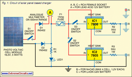
Savings on electricity bills can be achieved by utilizing alternative power sources. The photovoltaic module, or solar panel, described here has a power output of 5 watts and delivers 16.5V under full sunlight conditions, with a current output of...
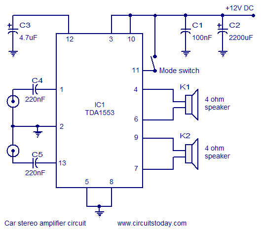
A car stereo amplifier circuit that can be used in automobiles, designed using the Class-B audio amplifier TDA1553, complete with a circuit diagram and schematics. The car stereo amplifier circuit utilizes the TDA1553, a Class-B audio amplifier known for its...
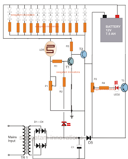
The following circuit is an LED emergency light circuit featuring advanced functionalities such as overcharge battery cut-off, daytime auto-disable, and automatic activation of the LEDs during AC mains failure, reverting to charging mode when power is restored. The circuit...