
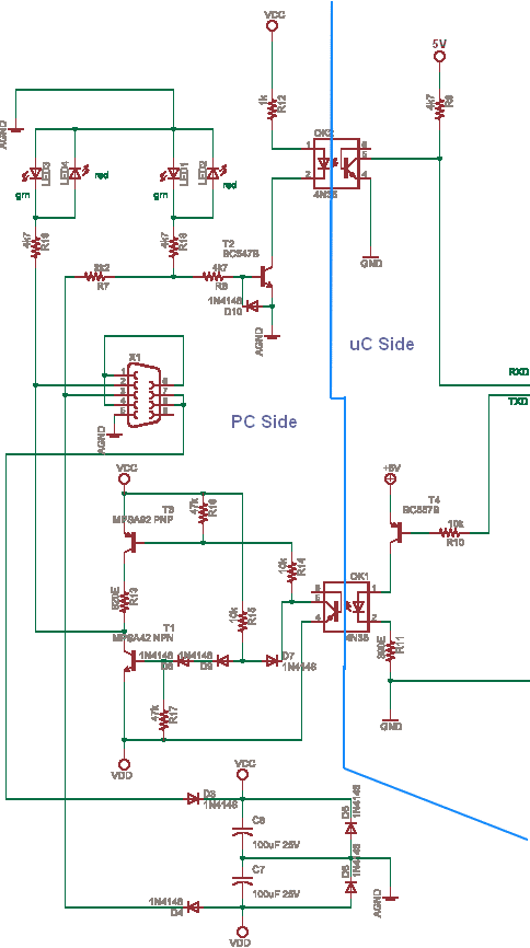
RS232 reciever schematic
The circuit operates by interfacing with the PC's serial port, utilizing standard RS-232 communication protocols. The design employs four CMOS chips, specifically configured to manage up to 8 outputs each. By cascading additional 8-bit shift registers, the total output capability can be expanded to control up to 32 channels. The optical isolator included in the design serves to protect both the circuit and the PC from voltage spikes or noise that may occur on the output lines, ensuring safe operation during the light show.
The circuit's simplicity and reliability are attributed to the use of CMOS technology, which not only reduces the number of components required but also enhances power efficiency. The integration of discrete components, such as resistors and capacitors, is crucial for establishing the necessary timing and signal conditioning for the serial communication.
The RS-232 serial communication is characterized by the transmission of voltage levels that represent binary data. In this circuit, the quiescent state of the line is held at approximately -12V, designating a logical "1". The data transmission is initiated by a start bit, followed by the data bits, and concluded with stop bits, which are essential for maintaining synchronization between the transmitting and receiving devices.
To ensure reliable operation, the circuit is designed to accommodate two stop bits, which provide ample time for the receiver to prepare for the next data frame. This design consideration is particularly important in environments where timing variations may occur.
In summary, this circuit effectively combines CMOS technology with RS-232 communication principles to create a robust solution for controlling a 32-channel Christmas light display, making it an ideal choice for festive lighting control applications.This circuit was designed to control a 32 channel Christmas light show from the PC serial port. Originally designed with TTL logic, it has been simplified using CMOS circuits to reduce component count. It is a fairly simple, reliable circuit that requires only 4 common CMOS chips (for 8 outputs), an optical isolator, and a few discrete components.
The schematic diagram (SERIAL.GIF) illustrates the circuit with 16 outputs which can be expanded with additional 8 bit shift registers. This circuit requires physical connections be made to the computer's serial port (COM1 or 2). To the best of my knowledge, it is difficult to cause damage to yourself or your computer by improper connections to this port, but there is no guarantee that damage will not result. Use caution when making any external electrical connections. Basic RS232 serial transmission Serial data is transmitted from the PC as a series of positive and negative voltages on a single wire which occur at predetermined times established by the baud rate.
Both the transmitter and receiver must be operating at the same baud rate so that the receiver knows when to expect the next bit of information. For the PC serial port, baud rate and bit rate are the same thing, but this is not necessarily true with modems that can detect more than two states of the line.
In the quiescent state, with no load on the line, the voltage on the transmit line (pin 2 of the 25 pin connector) will be about -12 relative to the signal ground (pin 7), which corresponds to a logical "1". The output impedance of the serial port is about 1K ohm which yields about 6 milliamps at 6 volts. A typical data transmission frame consists of a start bit, 8 data bits, and one to three stop bits.
The start bit which is always positive, signals the beginning of the transmission and is used by the receiver to synchronize the clock so that the data bits can be sampled at the proper times. After the 9th time interval passes (start bit plus 8 data bits) a dead time occurs which allows the receiver time to get ready for the next character.
This dead time is referred to as a stop bit, which is always negative or the same as the quiescent state. The circuit described here requires two stop bits of dead time for reliable operation. More sophisticated circuitry would require only one. 🔗 External reference
Related Circuits

These two circuits are multi-range timers that offer periods of up to 24 hours and beyond. They can function as repeating timers or single-shot timers. Both circuits are fundamentally the same, with the primary distinction being their behavior in...
The circuit incorporates isolation at the sensors and actuators to ensure that the PC is also isolated. Various chips are available for this purpose. The circuit is constructed with discrete and passive components, with the exception of the opto-isolator...
A simple LED-based voltmeter is required to monitor the voltage of a variable power supply. The proposed LED voltmeter circuit utilizes a series of light-emitting diodes (LEDs) to visually represent the voltage level of a variable power supply. This...
This circuit generates a two-tone effect similar to the cuckoo song. It can be used for doorbells or other applications due to a built-in audio amplifier and loudspeaker. As a sound effect generator, it can be connected to external...
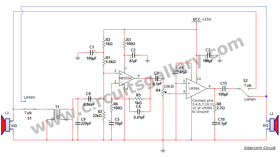
An intercom or intercommunication circuit is a two-way communication system that provides a reliable communication line and is easy to implement. The circuit consists of an amplifier, two switches, and two loudspeakers, allowing for the extension of the system...
This schematic has been developed as an exercise to learn about amplifiers. There are several aspects that require clarification and further understanding. The schematic in question likely involves a basic amplifier circuit, which may include components such as resistors, capacitors,...