
infrared motion detector

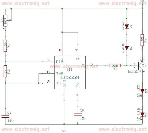
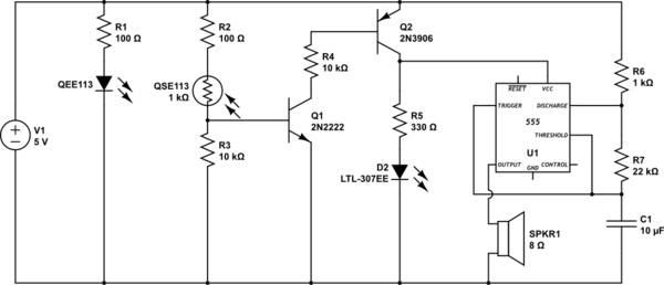
The infrared motion detector circuit operates on the principle of phase difference in reflected infrared rays. The NE 555 timer IC, configured as an astable multivibrator, continuously generates a square wave output at a frequency of 5 kHz. This output drives an infrared LED, which emits infrared light pulses. When these pulses strike an object, they are reflected back. If the object is stationary, the reflected infrared light maintains a consistent phase. However, if the object is in motion, the phase of the reflected light changes due to the Doppler effect.
The phototransistor (Q1) is positioned to receive the reflected infrared light. Under normal circumstances, the phototransistor does not detect any significant changes in the phase of the incoming light, resulting in a low output from IC2. When an intruder moves within the detection range, the phase difference in the reflected infrared light is detected by the phototransistor. This change is then processed by IC2, which is configured to recognize variations in the input signal.
Once IC2 detects the phase difference, it triggers a transition at output pin 7 from low to high. This output can be used to activate an alert mechanism, such as an LED or a buzzer, to indicate the presence of an intruder. The circuit can be fine-tuned with additional components, such as resistors and capacitors, to adjust sensitivity and response time, ensuring reliable operation in various environments. Overall, this infrared motion detector circuit provides an effective solution for security applications, utilizing simple components to achieve reliable motion detection.Here is the circuit diagram of an infrared motion detector that can be used to sense intrusions. Infra red rays reflected from a static object will be in one phase, and the rays reflected from a moving object will be in another phase. The circuit uses this principle to sense the motion. The IC1 (NE 555) is wired as an astable multivibrator. The IR diode connected at the output of this IC produces infrared beams of frequency 5Khz. These beams are picked by the infrared sensor, photo transistor Q1. At normal condition, that is, when there is no intrusion the output pin (7) of IC2 will be low. When there is an intrusion the phase of the reflected waveforms has a difference in phase and this phase difference will be picked by the IC2. Now the pin 7 of the IC 2 goes high to indicate the intrusion. An LED or a buzzer can be connected at the output of the IC to indicate the intrusion. 🔗 External reference
Related Circuits
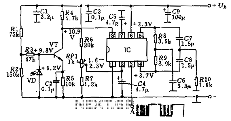
The circuit utilizes an integrated amplifier, resulting in a simple and compact design. The TDA4050 IC is employed, where a weak signal is received by the infrared photodiode (VD) and first passes through a transistor amplifier. The circuit is...
This Remote control Jammer device is useful when blocking someone from using the remote control (such as children who frequently change the channels on the TV). This remote control jammer is very simple and uses two infrared LEDs that...
This circuit detects when a tube is empty and pulses a piezo buzzer at 5-second intervals. It is currently operational with a 5V supply on a breadboard but needs to be adapted for a 12V supply from a wall...

The circuit depicted is designed to protect a system from power supplies that may exceed safe limits. An example of this is small consumer products that utilize external AC adapters, where there is a risk of accidentally connecting the...
This infrared transmitter utilizes pulse width modulation (PWM). The transmitter is equipped with an LM567 tone decoder circuit. An audio signal (at least 50 mV peak-to-peak) is amplified with transistor T1 and subsequently used to modulate IC1. The frequency...
This is a simple and easy-to-build gold detector circuit. The circuit is capable of sensing gold, metal, or coins from a distance of approximately 20 cm, depending on the size of the object being detected. It oscillates at around...