
Universal motor control

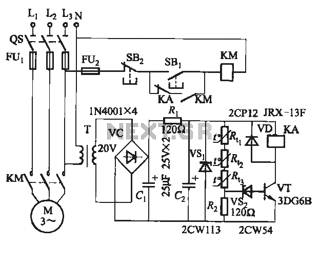
The described circuit utilizes two silicon-controlled rectifiers (SCRs) to control the operation of a motor based on a time delay mechanism. SCR1 is responsible for initiating the conduction phase, which subsequently removes the gate signal from SCR2, effectively halting the motor's operation when the predetermined time delay expires. This mechanism ensures that the motor runs for a specified duration before being switched off.
The time delay can be adjusted using potentiometer R2, which alters the charging time of capacitor C1. The time constant of the RC circuit formed by C1 and R2 determines how long it takes for the voltage across C1 to reach the gate trigger level of SCR1. A larger capacitance value for C1 can be employed to extend the time delay, allowing for more flexibility in applications requiring longer operational periods.
Motor speed control is facilitated by potentiometer R3, which adjusts the voltage supplied to the motor, thereby modulating its speed. This variable resistance allows for fine-tuning of motor performance based on load conditions.
In scenarios where the motor experiences heavier loads, it is advisable to replace SCR2 (GE-X1) with a more robust SCR, such as the C30B, to ensure that it can handle the increased current and voltage demands without failure. This substitution enhances the reliability of the circuit under varying operational conditions.
Overall, this circuit design provides an effective solution for controlling motor operation with adjustable time delays and speed, making it suitable for various industrial and automation applications.When the time delay expires, SCRl conducts and removes the gate signal from SCR2, which stops the motor. Both the time delay and motor speed are adjustable by potentiometers R2 and R3. If heavier motor loads are anticipated, use the larger C30B SCR in place of the GE-X1 for SCR2 Also, the capacitance of Cl can be increased to lengthen the time delay, if desired.
Related Circuits
The circuit features four pins labeled "Controller pin 1," "Controller pin 2," "Controller pin 3," and "Controller pin 4," which are responsible for controlling the motion and direction of the stepper motor based on the step sequence programmed into...
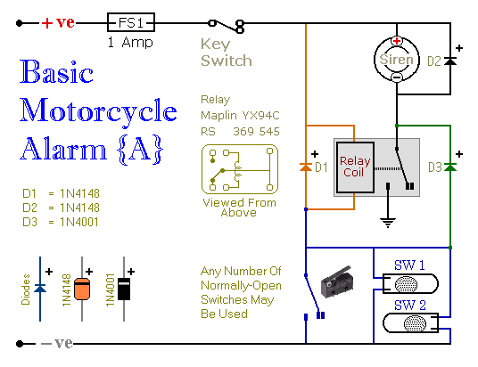
These are two easy-to-build relay-based alarms that can be used to protect motorcycles, among other applications. Using relays with 6-volt coils will safeguard a "Classic Bike." Both alarms are compact, with completed boards occupying approximately half a cubic inch...
The UBA2024 is a half-bridge integrated circuit (IC) and a 550 V lamp controller. This device features 9-ohm switches that support standard compact fluorescent lamp (CFL) applications up to 15 W. The UBA2024 is specifically designed for driving compact fluorescent...
A rotary 3-position, 3-pole switch. In one pole, a capacitor is connected to the other pole, with no bleeding from one capacitor to another. A rotary switch with three positions and three poles is a versatile component often used in...

This is a universal remote control that was constructed using 1KB of memory. It operates with televisions utilizing the RC5, RC80, and NEC protocols, which cover the majority of TV models. The remote has an effective range of approximately...
The semiconductor thermistor is an embedded thermal protection element that is sensitive to temperature, with a temperature error of 5 degrees. It offers reliability, a small size (diameter 3.5 mm), and ease of installation, making it suitable for embedding...