
motorcycle alarms numbers
The relay-based alarm circuits described are designed for versatility and ease of construction, making them suitable for various applications beyond motorcycle security. The compact nature of the boards allows for discreet installation, and the zero standby current ensures that the battery life is preserved. The choice of relay type provides flexibility in design, accommodating different user preferences and available components.
In both circuits, the use of mercury switches or micro-switches allows for tailored triggering mechanisms, ensuring that the alarm system is responsive to specific movements or unauthorized access. The option to configure the siren behavior—either continuous or momentary—adds a layer of customization, enabling the user to adapt the alarm system to their environment and preferences.
The inclusion of protective diodes (D1 and D2) is a critical design consideration, safeguarding the circuit from voltage spikes that could arise from relay actuation or sounder operation. This precaution is particularly important in systems where multiple electronic devices may share a power supply, ensuring that the integrity of all components is maintained.
The recommendation for moisture protection emphasizes the need for durability in outdoor environments. The installation of a fuse close to the power source is a standard practice in circuit design, ensuring that the wiring is protected from overcurrent situations, which could lead to potential hazards.
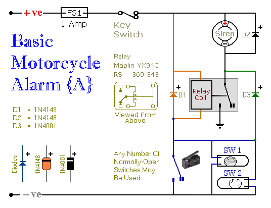
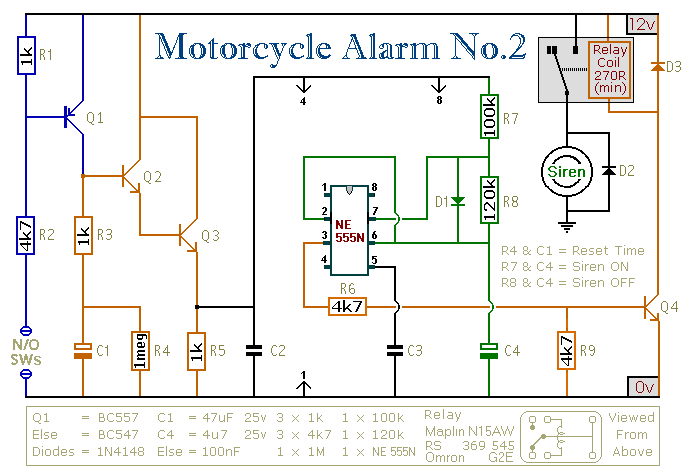
This alarm system can be adapted for various power sources, including dry batteries, making it versatile for different scenarios. The comprehensive support material provided with the alarm kits enhances the user experience, guiding the builder through the assembly process while ensuring that all necessary components are accounted for. Overall, these relay-based alarms represent an effective solution for securing motorcycles and other valuable assets.These are two - easy to build - relay-based alarms. You can use them to protect your motorcycle - but they have many more applications. If you use relays with 6-volt coils - they`ll protect your "Classic Bike". Both alarms are very small. The completed boards occupy about half a cubic-inch - 8 cc. The standby current is zero - so they won`t drain your battery. Circuit Number Five uses a SPCO/SPDT relay - but you really only need to use a SPST relay. If you are going to use the veroboard layout provided - you`ll need to use the style of relay specified. But you can build the alarm using whatever style of relay you have available. Any number of normally-open switches may be used. Fit the mercury switches so that they close when the steering is moved or when the bike is lifted off its side-stand or pushed forward off its centre-stand.
Use micro-switches to protect removable panels and the lids of panniers etc. When one of the trigger-switches is closed - the relay will energize and the siren will sound. You can choose what happens next. If you build the circuit as shown, the siren will continue to sound until you turn it off - or until the battery is exhausted. But, if you leave out D3 - the siren will stop sounding immediately the trigger-switch is re-opened. While you`re within earshot of your machine - the former configuration is best. You can always turn off the alarm yourself. But if you are going to be away from your bike for any length of time - and you don`t want to cause a nuisance - then the latter configuration is probably more suitable.
If you include a SPST switch in series with D3 - you can select the behaviour that best suits the circumstances at any given time. Relay coils and some sounders produce high reverse-voltage spikes that will destroy sensitive electronic components.
D1 and D2 are there to short-circuit these spikes before they can do any damage. Although there is nothing in the alarm circuit itself that could be damaged - I have no idea what other electronic equipment might be connected to the same power supply. So I included the two diodes as a precaution. If you`re satisfied that there`s nothing on your bike that might be damaged in this way - you can leave out the two diodes.
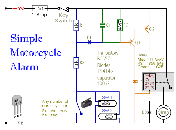
Circuit Number Six uses a DPCO/DPDT relay - but you really only need to use a DPST relay. If you are going to use the veroboard layout provided - you`ll need to use the style of relay specified. But you can build the alarm using whatever style of relay you have available. Any number of normally-open switches may be used. Fit the mercury switches so that they close when the steering is moved or when the bike is lifted off its side-stand or pushed forward off its centre-stand.
Use micro-switches to protect removable panels and the lids of panniers etc. When one of the trigger-switches is closed - the relay will energize and the siren will sound. You can choose what happens next. If you build the circuit as shown, the siren will continue to sound until you turn it off - or until the battery is exhausted. But, if you leave out the (yellow) solder-bridge in the top left-hand corner - the siren will stop sounding immediately the trigger-switch is re-opened.
While you`re within earshot of your machine - the former configuration is best. You can always turn off the alarm yourself. But if you are going to be away from your bike for any length of time - and you don`t want to cause a nuisance - then the latter configuration is probably more suitable. Connect a SPST switch in place of the (yellow) solder-bridge - and you can select the behaviour that best suits the circumstances at any given time.
Relay coils and some sounders produce high reverse-voltage spikes that will destroy sensitive electronic components. D1 and D2 are there to short-circuit these spikes before they can do any damage. Although there is nothing in the alarm circuit itself that could be damaged - I have no idea what other electronic equipment might be connected to the same power supply.
So I included the two diodes as a precaution. If you`re satisfied that there`s nothing on your bike that might be damaged in this way - you can leave out the two diodes. Whichever alarm you build - the circuit board and switches must be protected from the elements. Dampness or condensation will cause damage. Without the terminal blocks - the board is small. Ideally, you should try to find a siren with enough spare space inside to accommodate it. Fit a 1-amp in-line fuse as close as possible to the power source. This is Very Important. The fuse is there to protect the wiring - not the circuit board. Instead of using a key-switch you can use a hidden switch; or you could use the normally-closed contacts of a small relay.
Wire the relay coil so that it`s energized while the ignition is on. Then every time you turn the ignition off - the alarm will set itself. When the alarms are not sounding - the circuits use no current. This should make them useful in other circumstances - where a power supply is not readily available. Powered by dry batteries - with the relay and siren voltages chosen to suit - the alarms could be fitted almost anywhere. The Support Material for these alarms includes a detailed guide to the construction of the circuit-board, a parts list, a complete circuit description and more.
🔗 External reference
Related Circuits
When one of the switches is closed, the base of Q1 is connected to ground through D1 and R2. This activates Q1, which in turn activates Q2. Q2 connects the positive side of the relay coil to the supply...
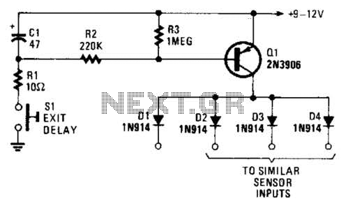
Depressing SI charges CI to the supply voltage. This biases Q1 on via bias resistors R2 and R3. A voltage is available for the duration of the delay period to hold off the alarm circuit. CI can be increased...
This is a small circuit that provides extra security for radio controlled models. When the signal from the transmitter fails, grab the circuit and set the servo connected to a preset position. The circuit is built around a CMOS...
This circuit features an intermittent siren output and automatic reset. It can be operated manually using a key switch or a hidden switch, and it can also be wired to activate automatically when the ignition is turned off. By...
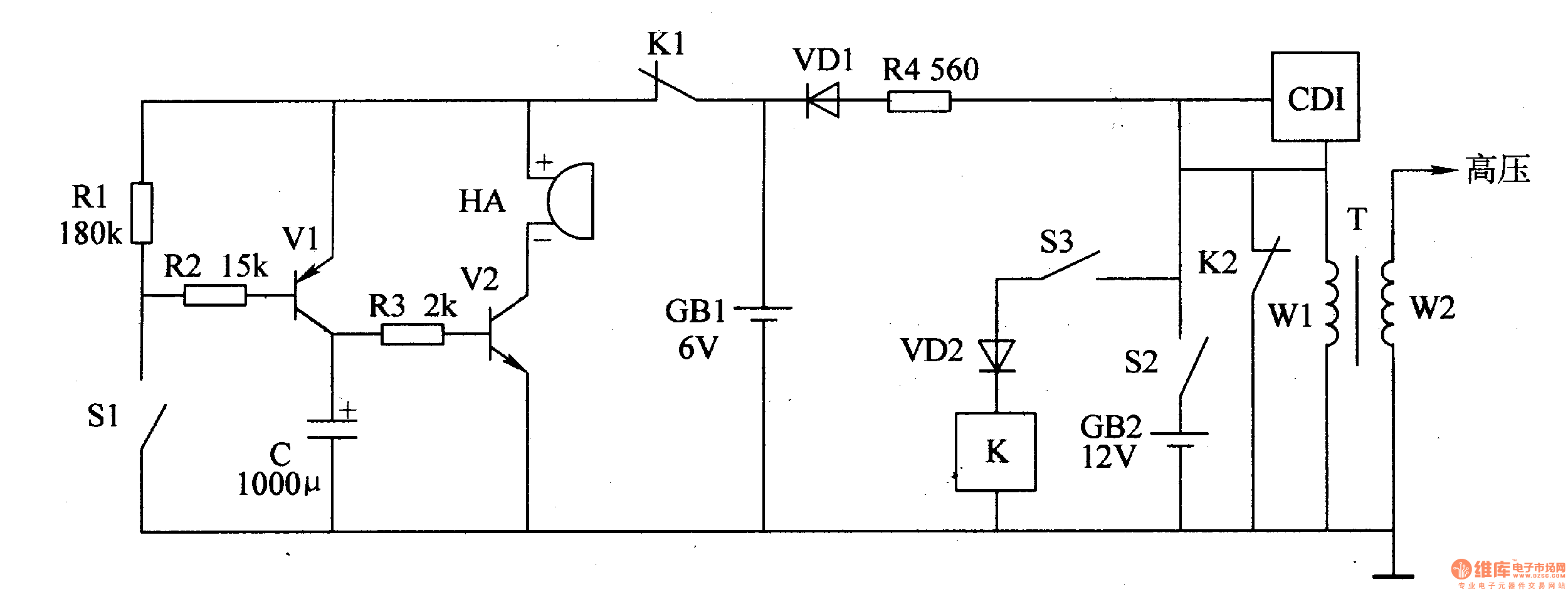
The motorcycle anti-theft alarm circuit consists of a detection alarm circuit, a charging circuit, and an anti-theft control circuit, as illustrated in figure 7-94. The detection alarm circuit includes a mercury switch (S1), resistors (R1-R3), a capacitor (C), transistors...
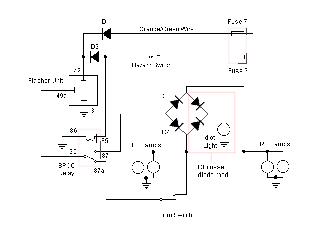
For some time, there has been a desire to incorporate a hazard flasher system into the Bonneville SE. After reviewing various discussions on this topic, a unique add-on system has been developed that functions correctly as hazard lights. This...
Warning: include(partials/cookie-banner.php): Failed to open stream: Permission denied in /var/www/html/nextgr/view-circuit.php on line 713
Warning: include(): Failed opening 'partials/cookie-banner.php' for inclusion (include_path='.:/usr/share/php') in /var/www/html/nextgr/view-circuit.php on line 713