
Stepper Motor Interface to Microcontroller
The described circuit utilizes an H-Bridge configuration to drive a bipolar stepper motor, allowing for precise control of the motor's motion and direction. The H-Bridge consists of four switches (typically MOSFETs or transistors) arranged in a bridge layout, enabling the application of voltage across the motor coils in both directions. This arrangement is essential for reversing the motor's direction, which is achieved by activating the appropriate controller pins in a specific sequence.
The controller pins are connected to the input terminals of the H-Bridge. When a high signal is sent to "Controller pin 1," it activates one side of the H-Bridge, allowing current to flow through one coil of the motor. Activating "Controller pin 2" simultaneously allows current to flow through the opposite coil, creating a magnetic field that causes the motor to step. The sequence of activating these pins determines the stepping pattern, which can be full-step, half-step, or micro-stepping, depending on the desired resolution and smoothness of the motor's operation.
The programming of the microcontroller involves defining the step sequence and timing for each pin activation. This can be achieved using a timer interrupt or a loop that iterates through the defined sequence, ensuring that the timing between steps is consistent with the motor's specifications. Proper timing is critical to prevent missed steps or stalling, particularly under load.
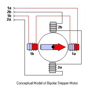
In summary, the circuit's design and the programming of the microcontroller work in tandem to achieve precise control of the bipolar stepper motor's motion. The implementation of an H-Bridge allows for versatile control of the motor's direction and speed, making it suitable for various applications in robotics, automation, and precise positioning systems.As you see in the circuit above the four pins "Controller pin 1", 2, 3 and 4 will control the motion and direction of the stepper motor according to the step sequece programmed in the controller. As already discussed in case of L293D, Here in this circuit too the four pins "Controller pin 1", 2, 3 and 4 will control the motion and direction of the ste
pper motor according to the step sequece sent by the controller. As we have studied that, Bi-polar stepper motors has 2 different coils. The step sequence for Bipolar stepper motor is same as that of unipolar stepper motors. The driving circuit for this require an H-Bridge as it allows the polarity of the power applied to be controlled independently. This can be done as shown in the figure below: Now we have seen the methods for connecting stepper motors with your microcontroller.
So keeping these circuits in mind, we will now look at the programming of microcontroller to control stepper motors. 🔗 External reference
Related Circuits
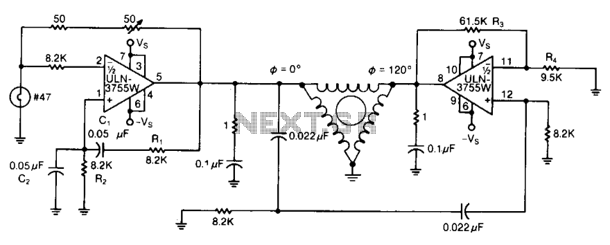
By varying either R1 or R2, the oscillator frequency can be adjusted over a narrow range. The R3/R4 ratio sets the second amplifier's gain to compensate for signal attenuation occurring in the phase shifters. The circuits can be driven...
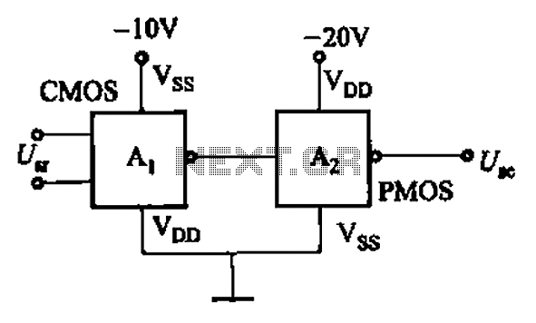
CMOS and PMOS cross interface circuit with PMOS integrated circuit providing high input impedance, allowing the input current to be negligible. The CMOS and PMOS interface circuit is illustrated in the accompanying figure. The CMOS and PMOS cross interface circuit...
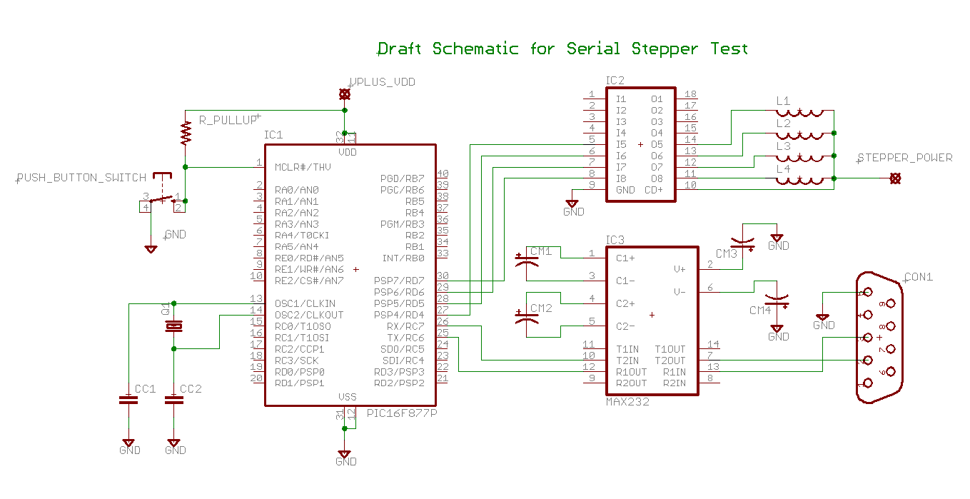
Determining the identification of drive wires on a unipolar stepper motor, which is commonly found in surplus or salvaged equipment. The platform utilized is a PIC16F877A microcontroller programmed with BoostC, interfaced via RS232 to a PC running a terminal...
This simple AVR programmer is capable of transferring hex programs to most ATMEL AVR microcontrollers. It is more reliable than many other simple AVR programmers available and can be constructed in a very short amount of time. This programmer...
This machine utilizes the FD-CAS-923 1-stepper motor control experiment board with a 4-phase stepper motor to avoid its schematic shown in Figure 4-42a. The JK1 cop 40 core flat cable connector allows for signal arrangements compatible with EICE51 simulation...
The ULN2003 features high voltage, high current Darlington arrays, each consisting of seven open collector Darlington pairs with common emitters. The ULN2003 is a versatile integrated circuit designed for driving high-current loads such as relays, motors, and lamps. It...
Warning: include(partials/cookie-banner.php): Failed to open stream: Permission denied in /var/www/html/nextgr/view-circuit.php on line 713
Warning: include(): Failed opening 'partials/cookie-banner.php' for inclusion (include_path='.:/usr/share/php') in /var/www/html/nextgr/view-circuit.php on line 713