
universal serial PC interface

The circuit design incorporates a MAX3232 level shifter, which effectively translates the RS232 voltage levels to TTL-compatible levels. This component is crucial for interfacing the RS232 signals with microprocessor logic levels. The AT90LS4433 microprocessor serves as the central processing unit, managing data flow between the RS232 interface and the digital/analog inputs and outputs. The microprocessor's architecture allows for efficient handling of both digital signals and analog readings, thanks to its built-in ADCs.
Connections to the circuit include the RS232 port, where the TX and RX lines interface with the MAX3232. The output from the MAX3232 feeds into the microprocessor's designated I/O pins, enabling seamless communication. The ADC channels are connected to the analog inputs, allowing for the measurement of voltage levels. The microprocessor executes firmware that interprets incoming RS232 commands and controls the digital outputs or processes analog inputs accordingly.
For power supply considerations, the circuit can operate within a voltage range of 3V to 5.5V, accommodating various applications. A regulated power supply is recommended to ensure stable operation, particularly when interfacing with sensitive components. The overall design is modular, facilitating easy integration into larger projects or standalone applications, making it an attractive solution for hobbyists and developers alike.Well, I guess every hobbyist some when comes up with ideas of controlling or measuring something with a PC. Of course the idea is tempting, there are so many easy-to-learn program languages available for PCs today that almost everyone can write the software to switch on the light when he is on vacation, to control these cute little toy robots or t
o measure the amount of rain over the day. So if you are a somewhat advanced hobbyist, the application is only limited by your fantasy (i. e. the sky is the limit). But: How can we close the gap between a few lines of software code and a real electrical signal outside of the computer Of course there are many solutions to this problem, many of them require serious "hacking" to access one of the i/o ports of a computer. (Especially Windows NT4 required very advanced programming skills if you wanted to use i/o ports for non-standard applications).
One port that is easy to access from a software point of view is the serial RS232 port (COM1, COM2, etc. ). All modern software development tools support the RS232 port, so its usually no problem at all to send or receive data via this port.
What makes the RS232 very unattractive for hobbyists is the fact the data bits are in a serial time synchronous format with critical timing and a relatively complex start/stop-bit overhead. To make it even worse the bit levels are -12V for high and +12V for a low bit, so connecting RS232 signals to a circuit that uses 5V logical levels is not trivial either.
Simply forget about connecting the RS232 directly to a relay driver stage or things like that. And that is where this circuit comes in. It converts a RS232 bit stream into standard digital signal inputs and outputs. It even provides you with a couple of 10bit ADCs so you can read analog voltage levels into your PC with a resolution of 1024 different levels. First of all the RS232 levels are converted to normal logical levels by a MAX3232. This is a standard IC that includes voltages converters which are able to produce 2xVcc and -2xVcc. Even if you use only 3. 2V as Vcc, it will give you somewhat over plus and minus 6 volts, that is more than sufficient for a reliable operation of the RS232 port.
I have used Vcc=3. 2 Volts but I assume for most of you it is more convenient to use Vcc=5V since that will give you standard TTL level signals at the in/out ports. Since the ADC has a resolution of 10bits, the max. value it can deliver is 3FF hex. That value always corresponds to a input level that is equal to Vcc. Feel free to choose any Vcc voltage between 3Volts and 5. 5Volts, both ICs will work fine in that range according to their specification. The second step is the conversion from parallel digitial data bit into the RS232 serial bit stream and vice versa.
For that we use a AT90LS4433 8bit microprocessor. It has a hardware-implemented RS232 port, a number of general purpose digital i/o-ports and internal 10bit ADCs. All it takes to make the whole thing flying is a software for the micro that reads commands from the RS232 port and reads/sends bits and/or reads analog voltage levels.
🔗 External reference
Related Circuits
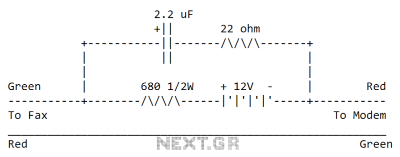
The circuit can be easily built to a small plastic box with telephone connectors in both ends. The circuit takes about 10-20 mA current, so if the circuit is not in use all the time it is best to...
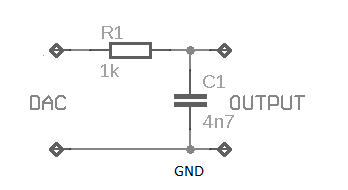
This weblog discusses electronic circuit schematics, PCB design, DIY kits, and electronic project diagrams. The subject circuit is a quality preamplifier with a built-in USB DAC designed for the Leachamp power amplifier. The schematic is based on the PCM2902...
Building a serial voltage meter to measure from 0 to 5 volts DC is straightforward. Utilizing MeLabs PicBasic and Microsoft Visual Basic Version 5 Pro is essential, as the MSComm control required for communication is not available in the Visual...
The circuitry of the ZXInterface2 is straightforward, consisting of a single custom-made integrated circuit (IC) that handles address decoding for the dual joystick interface. The ROM cartridge socket provides access to signals already present at the Spectrum's edge connector....
DC power must be supplied to the instrument through either specialized cabling or an internal battery. This should not be applied to collectible instruments that do not include onboard electronics. It can be conveniently implemented using a field effect...

The circuit involves a smart temperature control system utilizing DS1620 temperature sensors with a three-wire serial interface for managing a small electric heater. When the CD4044 type RS flip-flop is set to 1, the output Q becomes high, which...