
A circuit diagram of a phase comparator
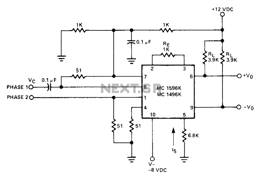
The described circuit employs a Signetic balance modem connection that leverages a transistor array functioning as a phase detector. This arrangement is critical for determining the phase relationship between the input signal and a reference signal. The output of the phase detector is proportional to the cosine of the phase angle, which is indicative of the frequency characteristics of the input signal when processed through the integrated circuit (IC).
In this configuration, the IC generates a total frequency difference, which is the result of the interaction between the input signal and the reference signal. This frequency difference is essential for various applications, including communication systems where phase modulation is utilized. The circuit effectively filters out the direct current (DC) component, which is considered extraneous for the purpose of phase detection. Instead, it focuses on the alternating current (AC) components that are directly related to the phase angle.
The transistor array serves as a crucial element in this circuit, providing the necessary gain and switching capabilities to accurately detect and process the phase information. The arrangement of transistors can be configured to optimize performance, ensuring that the output is a reliable representation of the phase differences present in the input signals.
This phase detector circuit can be integrated into larger communication systems, where precise phase measurements are vital for maintaining signal integrity and synchronization. The ability to extract phase information from the input signals allows for improved modulation schemes and enhances overall system performance. Circuit Description: Signetic balance modem connection transistor array as a phase detector, which contains information about the output of the cosine of the phase angle, equal to the frequency of the input signal plus IC, generating total frequency difference frequency. The difference between the direct current component becomes useless sum of the components associated with the phase angle.
Related Circuits
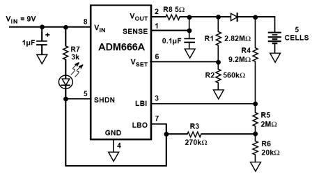
NiMH charger circuit diagram using ADM66A. Related searches include charger circuit, NiMH charger circuit, lead acid battery charger circuit, LiPo charger circuit, automatic battery charger circuit, simple battery charger circuit, lithium battery charger circuit, charger circuit diagram, and 12V...
The sound produced mimics the rise and fall of an American police siren. When first powered on, the 10µF capacitor is discharged, and both transistors remain off. Upon pressing the push button switch, the 10µF capacitor begins to charge...
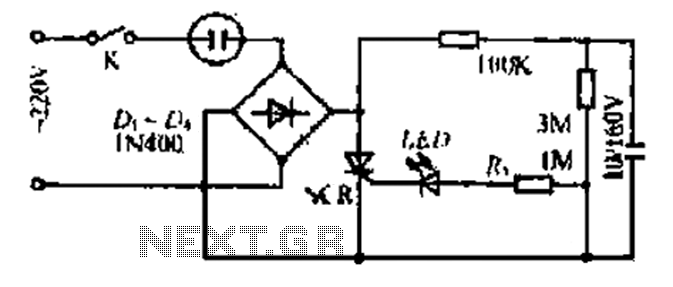
20V child-friendly power supply circuit for a foreign vine wine light, including a bulb and plug. The circuit features a bridge rectifier. The lamp access point is designed for a 10-100W bulb with a compact size. The output is...
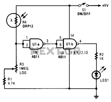
Two gates of a 4011 IC are utilized as a comparator. When the resistance of R4 decreases, the voltage at pins 1 and 2 increases, resulting in a logic zero at pin 3. This causes pin 4 to go...
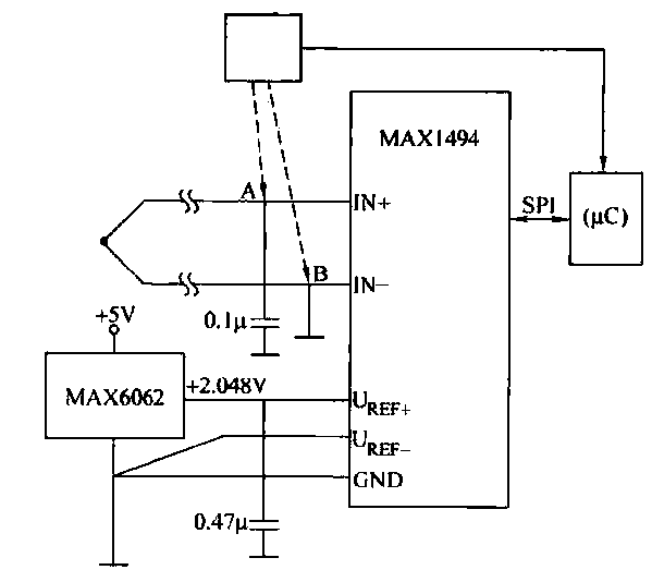
The circuit consists of the MAX1494 and a thermocouple temperature measurement system. The MAX1494 is terminated at 1N GND 5-32. An external temperature sensor, such as the DS75, can be utilized for junction temperature compensation. The MAX1494 employs an...
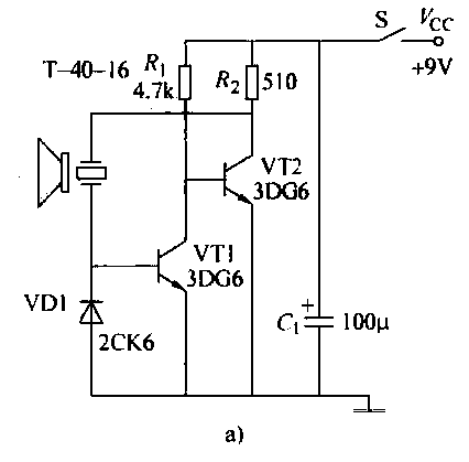
The ultrasonic transmitter circuit T-40-16, along with various discrete components, functions as a feedback sensor. The transistors VT1 and VT2 create a robust positive feedback oscillator that converts an electric signal into an ultrasonic oscillation signal, with the oscillation...