
usb 5v to 12v dc dc step up converter
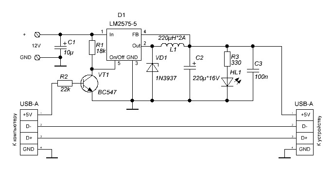
The described circuit operates as a DC-DC boost converter that efficiently steps up a 5V input voltage to a higher output voltage of 12V. This is particularly advantageous for applications where devices require a higher voltage than what is provided by standard USB power sources. The LT1618 voltage controller plays a critical role in regulating the output voltage and current.
In its operation, the circuit begins in a low-power state, supplying 100mA until a device is detected. Upon detection, the circuit can switch to a higher current supply mode, allowing for a maximum output current of 500mA. This feature is essential for applications that may draw more power once a device is fully engaged.
The circuit's design incorporates feedback mechanisms to monitor the load conditions continuously. As the load demand increases, the feedback loop adjusts the output voltage to maintain a constant input current. This is crucial to prevent damage to the circuit and connected devices due to overcurrent conditions. The ability to maintain a specific input current while adjusting the output voltage ensures stable operation under varying load conditions.
For example, in scenarios where the load is light (35mA), the circuit can maintain the output voltage at the desired 12V. However, if the load demand increases beyond the threshold (50mA in this case), the circuit dynamically adjusts the output voltage down to 8V to keep the input current steady at 100mA. This adaptive response is a key feature of the circuit, ensuring reliable operation across a range of devices with varying power requirements.
Overall, this boost converter circuit is an effective solution for powering devices that require higher voltage from a USB source, providing flexibility in current supply modes and maintaining stable operation through intelligent feedback mechanisms.This is a 5V to 12V DC-DC step-up (boost) converter circuitry that is especially ideal for the USB powered applications. First of all a USB port has two current supply modes. Before detecting the connected device, it supplies maximum 100mA to the load. After recognizing the device, it increases the output current up to 500mA. In this circuit, cont roller (LT1618) also provides two input current modes. 100mA and 500mA input modes can be selected by the user. Output currents are limited due to the increased potential difference at the output. When the demand of the load increases, output voltage will start to decrease. For example, if the circuit operates in the 100 mA input mode, when the load is 35 mA, the output voltage will be kept at 12V. But if the load increases to 50 mA, output voltage will reduce to 8V to maintain the constant 100 mA input current.
🔗 External reference
Related Circuits
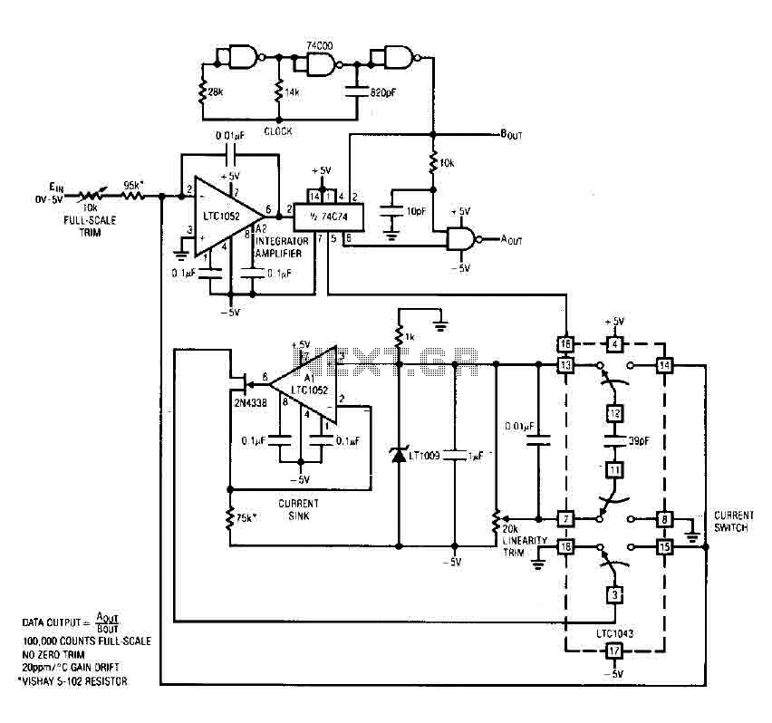
The circuit is an analog-to-digital (A/D) converter that consists of an operational amplifier (A2), a flip-flop, several logic gates, and a current sink. It employs a current balancing technique. The LTC 1052 is utilized for stabilization, ensuring that the...
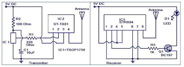
The IR to RF transmitter circuit described here can convert infrared (IR) signals from a remote control into radio frequency (RF) signals, allowing for long-distance transmission. This circuit effectively extends the range of an IR remote control and does...
This is a simple RS232 Serial to USB Converter. The RS232 to USB converter is an essential interface device that allows communication between devices with RS232 serial ports and modern computers that utilize USB ports. This converter is particularly useful...

An analog-to-digital converter (ADC) transforms an analog input voltage into a digital value. This circuit illustrates the operation of an ADC, utilizing the ATmega8 microcontroller to control its functionality. The resolution of the converter denotes the number of discrete...
Additional power supply for USB devices. Refer to the page for an explanation of the related circuit diagram. The additional power supply for USB devices is designed to enhance the power availability for devices that may require more current than...
This circuit measures the distance covered during a walk. The hardware is housed in a small box that can be slipped into a pocket. The display is arranged such that the leftmost display, D2 (the most significant digit), shows...