
USB Development Board
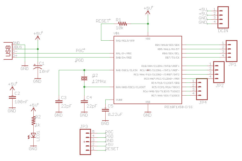
The described circuit is centered around the PIC18F14K50 microcontroller, which is designed for USB applications. This microcontroller operates at a maximum clock frequency of 48 MHz, provided by an external 12 MHz crystal oscillator. The crystal oscillator is essential for maintaining accurate timing for USB communication and other time-sensitive tasks.
The USB interface allows the microcontroller to function as a Human Interface Device (HID), enabling it to communicate with computers and other USB hosts. Common applications include interfacing with devices such as keyboards, mice, and various sensors. The limitations of the PIC18F14K50 become apparent when considering USB mass storage; due to its memory constraints, this microcontroller cannot support USB flash drives or similar storage devices.
The board design is minimalistic, focusing on essential components. In addition to the PIC18F14K50 and the 12 MHz crystal, a USB connector is included for power and data communication. The inclusion of an ICSP (In-Circuit Serial Programming) header allows for programming and debugging of the microcontroller directly on the board, facilitating development and testing.
Power management is a critical aspect of the design, as the board is powered via USB. The current consumption must be monitored to ensure it does not exceed 500 mA, which is the maximum current draw specified for USB devices. This consideration is vital for maintaining compliance with USB standards and preventing potential damage to both the board and the host device.
The board's layout is designed for ease of integration into prototyping environments, such as breadboards. It features headers for connecting wires and breakout boards, providing flexibility for various applications. The absence of a RESET switch simplifies the design further, as many USB devices, such as mice, do not require a reset mechanism in normal operation. Overall, this circuit serves as a compact and efficient solution for developing USB HID applications using the PIC18F14K50 microcontroller.A little board with most of Microchip kit, but less parts then all these boards. Only the basic components to get the microcontroller up and running the Microchip USB Library examples. PIC18F14K50 is a really basic device and after some research I found what you can do and what you can not do with it: What you can do: USB HID (Human Interface Devices) like mouse, keyboards, sensors, serial-usb converters, etc.
What you can not do: USB storage devices, like USB flash drives. USB storage is a problem because of memory limitations on PIC18F14K50 family. The circuit design is very simples. Basically all you need is PIC18F14K50; 12MHz Crystal; USB connector;The circuit still have a ICSP header for device programming and debugging. It's USB powered, so you can pay attention on current drain (500mA max.). The board is very simple and clean. I want a little device to put on breadboard or stay alone, with headers to connect wires and breakout boards. I don't put a RESET switch on board because I think it's not necessary (does your mouse have a reset button?).
🔗 External reference
Related Circuits
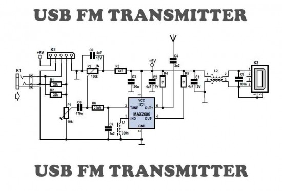
This is a simple USB FM transmitter designed to play audio files from an MP3 player or computer on a standard VHF FM radio. The USB FM transmitter operates by converting audio signals from a digital source, such as an...
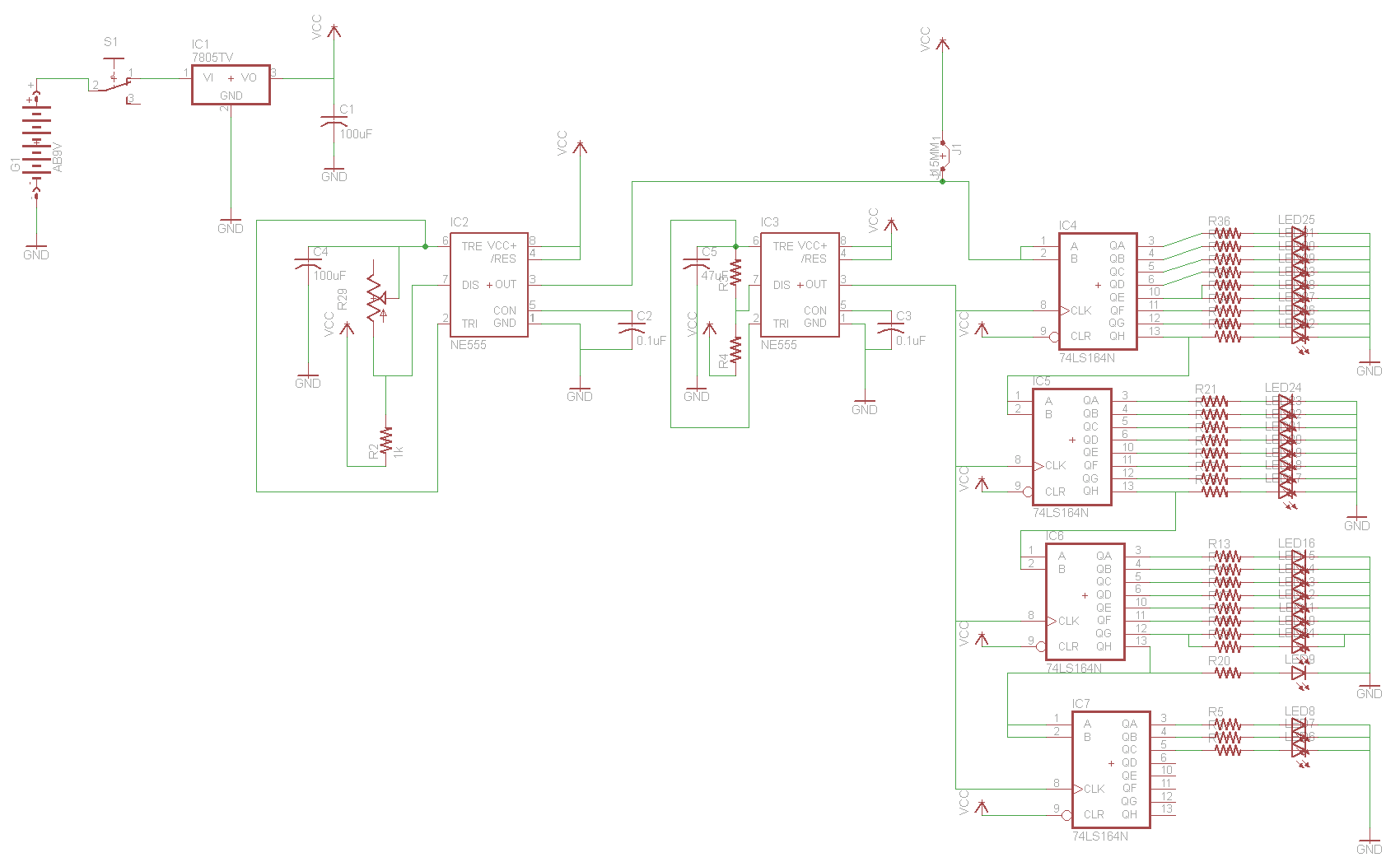
For the two-layer board schematic, six core integrated circuits (ICs) will be utilized: four 74LS164 shift registers and two 555 timers. The schematic will be constructed using the Eagle Layout Editor, as all required components are available in its...
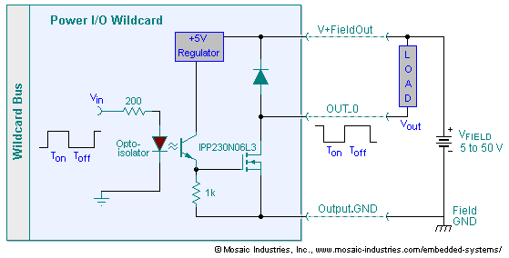
The embedded I/O board offers isolated high voltage switch inputs and eight high current, high voltage DC outputs. It utilizes optically isolated, open drain N-MOSFET transistors functioning as solid state relays (SSR) to control various resistive or inductive loads....
This article aims to utilize an old PC as a simple controller. Many outdated PCs, such as the 8088, 8086, 80286, 80386, or even 80486, have become obsolete systems. This design employs an 8-bit LPT printer parallel data port...
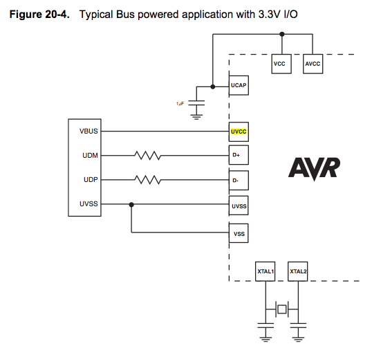
Since the microcontroller unit (MCU) is powered through USB, the common zero voltage should align with the supply voltage and thus be connected to the 0V (UVSS) line. In electronic circuit design, it is essential to ensure that the ground...
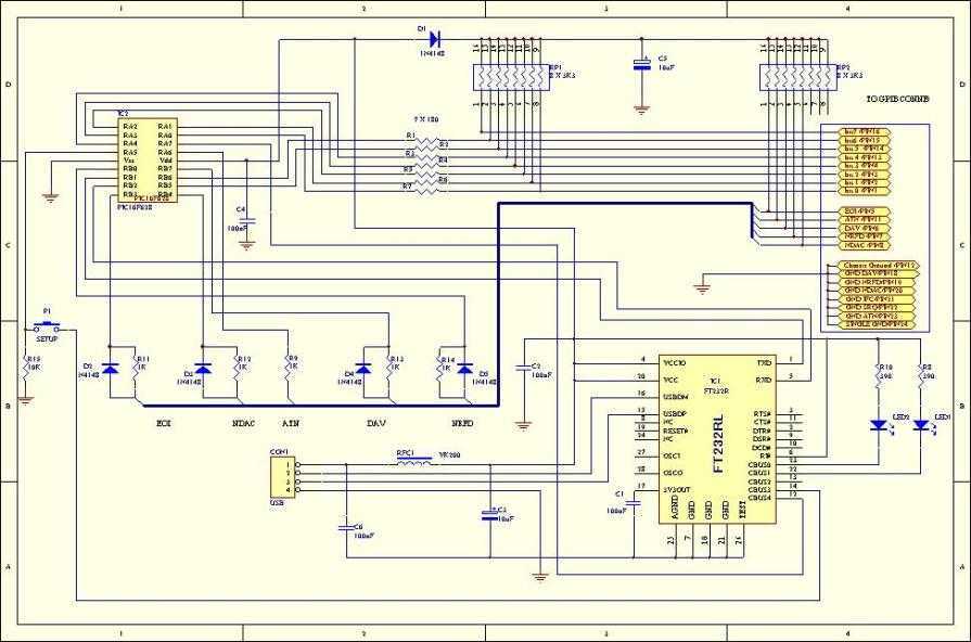
This adaptor will capture plots or prints of your GPIB instrument to your PC through the USB port. It fills the need of anybody who has a test instrument with the GPIB port and likes to get the screen...