
USB Digital Setting Circles
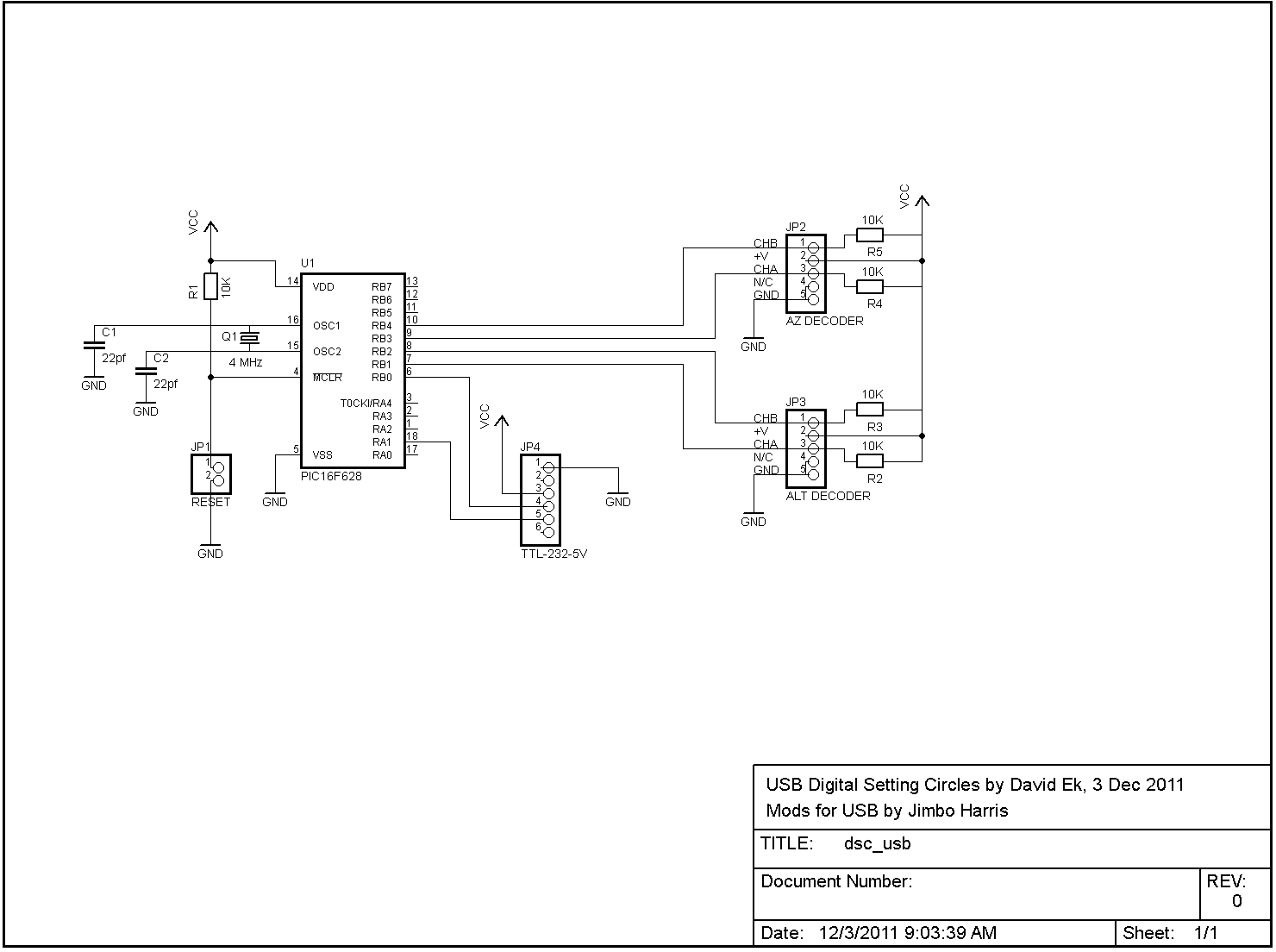
The modified DSC circuit integrates a USB-serial conversion cable, specifically the FTDI TTL-232R-5V, to facilitate direct communication between the PIC microcontroller and a PC. This design choice streamlines the circuit by eliminating the MAX232 chip, which was previously necessary for converting TTL signals to RS-232 levels, along with the associated capacitors. The reliance on USB power simplifies the overall power management, making the circuit more compact and efficient.
In terms of component modifications, the removal of pull-up resistors on unused I/O pins of the PIC microcontroller reduces unnecessary power consumption and board complexity. The transition from a four-pin oscillator to a crystal oscillator enhances the stability and accuracy of the clock signal driving the PIC, which is crucial for maintaining timing in embedded applications.
The substitution of the PIC16F84 with the PIC16F628 not only reduces costs but also maintains functionality, although it requires corresponding updates to the firmware to ensure compatibility with the new microcontroller. The absence of the DB9 connector further streamlines the design, as the 6-pin JP4 connector provides a direct interface for the TTL-232R-5V cable, promoting an easier connection to the PC.
Overall, the adaptation of the DSC circuit for USB operation results in a more user-friendly and efficient design, suitable for various applications that require serial communication without the complexity of traditional RS-232 interfaces. The availability of a kit from FAR Circuits allows for straightforward assembly, making it accessible for hobbyists and professionals alike.The serial version of the DSC circuit described in these pages is readily adapted to use with a USB-serial conversion cable. In fact, FTDI makes the TTL-232R-5V cable that converts TTL-level serial data coming straight from the PIC into USB for the PC.
Using this cable allows us to eliminate the MAX232 chip (and several capacitors) used in the ser ial circuit that converts TTL to RS-232 and back. At also allows us to eliminate the external power supply and the components making up the voltage regulator for the board. Instead, we draw power from the USB port itself. While updating the original circuit for USB, it made sense to make a couple of other changes. Most noticeable is the elimination of the pull-up resistors on the unused PIC I/O pins. Less obvious is the change from the four-pin oscillator to a simple crystal for clocking the PIC. Finally, the original PIC16F84 was replaced by an equivalent but cheaper part, the PIC16F628 (requiring updated hex code ).
And, of course, there`s no longer a DB9 connector on the board for a serial port. Instead, 6-pin connector JP4 is the connection point for the TTL-232R-5V cable. The result is that the USB version of the circuit is considerably simpler than the serial version. FAR Circuits sells a kit for this circuit that includes a PC board and all board-mounted parts and connectors, but not the TTL-232R-5V cable. You`ll need to purchase the TTL-232R-5V cable separately. Both Mouser and DigiKey sell this cable for about $20 plus shipping. Go here for information on how to order the kit from FAR Circuits. 🔗 External reference
Related Circuits
The adapter is based on the FTDI USB/serial IC FT-232BM. It has been successfully tested with various transceivers and software, including the VX-7R (using VX-7R Commander), FT-8900 (via FTB-8900), FT-817 (with FT-817 Commander and Ham Radio Deluxe), and IC-706MkIIG...
This document describes the function of a digital stopwatch that counts from 0 to 99 seconds. The stopwatch utilizes four integrated circuits from National Semiconductor, although alternative components could achieve similar results. The circuit diagram is presented in an...
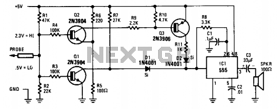
The probe's input circuit detects the signal condition and generates a low-pitched tone for low-level signals (below 0.8 V) or a high-pitched tone for high-level signals (above 2 V). The tone probe employs sound to indicate the status of...
This USB circuit utilizes an integrated circuit (IC) to convert digital voice data into an analog format, making it suitable for headphone use. Additionally, the output can be amplified through a power amplifier, allowing the sound to be played...
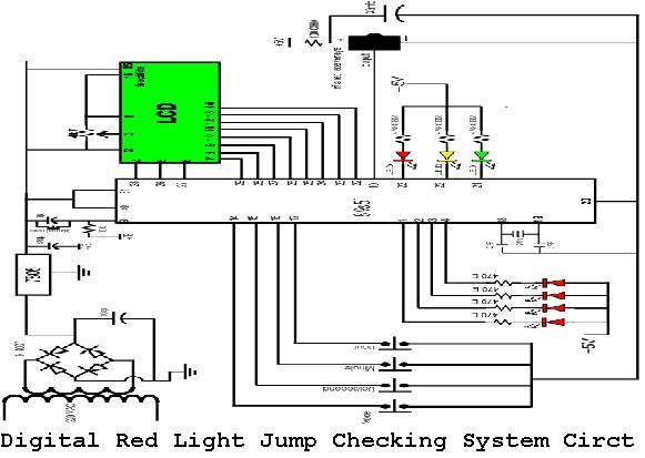
A digital red light jump checking system with an RF transmitter. This project allows for the tracking of vehicles that run red lights by capturing their license plate numbers and the time of the violation. The digital red light jump...
This circuit measures the distance covered during a walk. The hardware is housed in a compact box that can be conveniently placed in a pants pocket. The display is designed as follows: the leftmost display, D2 (the most significant...
Warning: include(partials/cookie-banner.php): Failed to open stream: Permission denied in /var/www/html/nextgr/view-circuit.php on line 713
Warning: include(): Failed opening 'partials/cookie-banner.php' for inclusion (include_path='.:/usr/share/php') in /var/www/html/nextgr/view-circuit.php on line 713