
Tone probe for testing digital ics
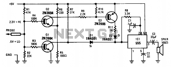
The probe's input circuit is designed to monitor electrical signals and provide auditory feedback regarding their levels. It operates by utilizing a comparator circuit that evaluates the input voltage against predefined thresholds. When the input voltage falls below 0.8 V, the circuit activates a low-frequency oscillator, producing a low-pitched tone. Conversely, when the signal exceeds 2 V, the circuit switches to a high-frequency oscillator, generating a high-pitched tone.
The circuit typically consists of several key components: a voltage divider to scale the input signal, an operational amplifier configured as a comparator, and a piezoelectric speaker or buzzer for sound output. The voltage divider ensures that the input signal is within the operational range of the comparator, while the operational amplifier provides the necessary gain and switching capability.
Additionally, the design may include a microcontroller to enhance functionality, allowing for adjustable thresholds, signal processing, and possibly visual indicators, such as LEDs, to accompany the audible tones. This combination of sound and visual feedback aids in the effective monitoring of signal conditions in various electronic applications, such as troubleshooting and maintenance tasks. The tone probe serves as a valuable tool for engineers and technicians, providing immediate and intuitive feedback on signal status. The probe's input circuit senses the condition of the signal and produces either a low-pitched tone for low-level signals (less than 0.8 V) or a high-pitched tone for high-level signals (greater than 2 V). The tone probe uses sound to tell the status of the signal being probed. 🔗 External reference
Related Circuits
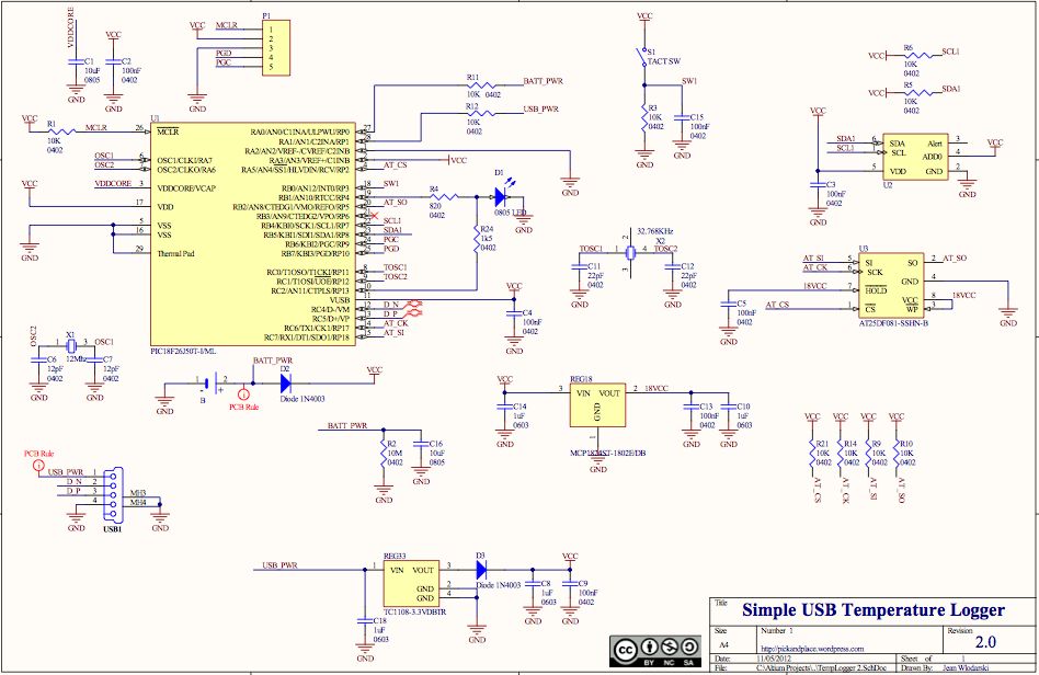
The receiver circuit and display module will receive the high-frequency AC power cord and decode it to provide actual temperature readings using digital IC No. CD4553 (Three-digit BCD Counter IC) and IC CD4511 (BCD-to-7-Segment Latch/Decoder/Driver IC). The frequency pulses...
With this circuit, we can have an acoustic clue, frequency 2kHz, when we have a short vibration at its input. It is constituted from a monostable multivibrator (with Schmitt trigger inputs), with a duration roughly 100ms, oscillator TTL, that...
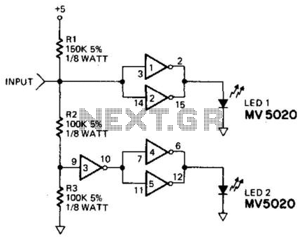
This logic probe utilizes a CD4009 CMOS hex inverter. The high-input impedance characteristic of CMOS technology prevents loading of the circuit under test. Since the output of the inverters is not defined at either a high or low level...
The source code features a FAT12 filesystem that can be utilized to create custom flash drives for various projects. This source code is based on the Microchip Applications libraries for the Device Mass Storage SD Card data logger using...
When a couple moved into their small apartment in San Francisco, they wanted to create a compact liquor cabinet and wine rack. After a visit to IKEA, they acquired a bookshelf that could be easily transformed into a stylish...

The circuit is a decay feedback tone control circuit that incorporates anti-attenuation feedback action. Its primary function is to enhance or attenuate bass frequencies, although this distinction can sometimes be challenging to perceive. The analysis utilizes the superposition theorem,...