
USB Fuse
The MAX1562 is designed for integration into various USB-powered devices, ensuring that they operate safely without risking damage to the host system. The low power consumption during normal operation and standby mode makes it suitable for battery-operated devices as well. The internal MOSFET's low on-resistance minimizes power loss, enhancing the efficiency of the device.
The current limiting function is particularly critical in applications where multiple USB peripherals may be connected to a single port, as it prevents excessive current draw that could lead to thermal failure or damage. The adjustable current limit feature allows designers to tailor the device for specific applications, ensuring optimal performance while maintaining safety.
In terms of thermal management, the built-in thermal cutoff provides an additional layer of protection, making the MAX1562 a robust choice for applications where temperature fluctuations may occur. The visual feedback provided by the LED through the FAULT output offers a simple yet effective way for users to monitor the operational status of the device, enhancing user experience and reliability.
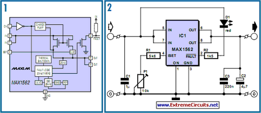
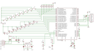
Overall, the MAX1562 is a versatile and essential component for modern USB-powered devices, combining functionality, safety, and efficiency in a compact package.Life in the 21st century would be almost unbearable without some of the computer peripherals that PC users now look on as essentials - take for example the USB powered teacup warmer; this device is obviously an invaluable productivity tool for all users but it could prove a little tire some if the extra current it draws from the USB port is suffic ient to produce a localised meltdown on the motherboard. In a slightly more serious vein a similar situation could result from a carelessly wired connector in the design lab during prototyping and development of a USB ported peripheral. What`s needed here is some form of current limiting or fuse to prevent damage to the motherboard. The MAX1562 shown in Figure 1 is a purpose-built USB current limiter from the chip manufacturers Maxim.
The device operates with a supply voltage from 4. 0 to 5. 5 V with an operating current of typically 40 µA or 3 µA in standby mode. The circuit introduces a very low resistance in the power line (typically 26 m but guaranteed less than 50 m) from an internal MOSFET. The FET gate bias voltage is generated on-chip from a charge pump circuit. The chip can distinguish between an overload and a short circuit condition in the supply line by measuring the voltage drop across its internal resistance; if the voltage is less than 1 V a short circuit is assumed and the chip pulses a (limited) output current every 20 ms in an effort to raise the output voltage.
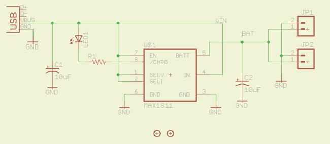
This approach will eventually be successful if the short circuit was caused by a large value capacitor across the USB supply pins or an external hard drive which have a high in-rush at start up. If the supply rail is not pulled up within the first 20 ms the FAULT output (pin 2) is driven low. The output current limit is set by a single resistor on pin 4 (ISET): LIM = 17120 / RSET. The circuit diagram shows a fixed 5. 6k resistor in series with a 10k preset giving an adjustable current limit between 1. 097 and 3. 057 A. This range should be sufficient for the majority of applications. Increasing the preset resistance reduces the current limit level. Any intermittent connection in the preset (caused by a dirty track etc. ) will switch the chip into shut down. The MAX1562 also contains a thermal cut out which turns off the output when the chip temperature exceeds 160 degrees C.
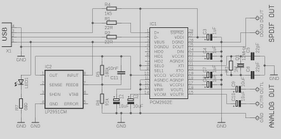
Figure 2 shows a diagram of the manufacturer`s application circuit. The FAULT output drives an LED via a series limiting resistor which reduces the LED current to 2 to 3 mA. The MAX1562 is available in a HESA variant (with an active high ON signal) or ESA version (with an active low ON signal).
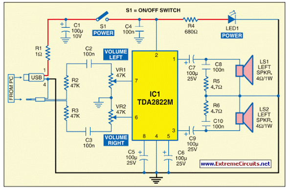
The chip is packaged in an 8-pin SMD outline. Figure 3 shows a small PCB layout for the circuit using mostly SMD components. 🔗 External reference
Related Circuits
Lithium Polymer Batteries are a very common source of power today. Many electronics gadgets have one inside, and they have some reasonable features. I've bought great batteries, with different sizes and capacities for my electronics projects. So long I'm...
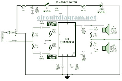
This is the circuit diagram of a USB-powered computer speaker, commonly referred to as multimedia speakers for PCs. The circuit features a single-chip design, operates on a low-voltage electrical power supply, is compatible with USB power from computers, includes...
This is a 5V to 12V DC-DC step-up (boost) converter circuit that is particularly suitable for USB-powered applications. Initially, a USB port has two current supply modes. Before detecting the connected device, it supplies a maximum of 100mA to...
A USB solution is required for a project utilizing the LPC2148 microcontroller (MCU). In the past, interfaces such as LPT or COM were commonly used to connect projects to a PC, but these have become obsolete. The project allows...
This is a high-quality preamplifier circuit with a built-in USB DAC designed for the Leachamp power amplifier. The schematic is derived from the PCM2902 datasheet. The circuit includes a DAC and ADC, SPDIF output and input, and an HID...
This circuit of multimedia speakers for PCs features a single-chip design, operates on a low-voltage power supply, is compatible with USB power, and allows for easy heat dissipation. The multimedia speaker circuit is designed to enhance audio output for personal...
Warning: include(partials/cookie-banner.php): Failed to open stream: Permission denied in /var/www/html/nextgr/view-circuit.php on line 713
Warning: include(): Failed opening 'partials/cookie-banner.php' for inclusion (include_path='.:/usr/share/php') in /var/www/html/nextgr/view-circuit.php on line 713