
IrDA Interface
The infrared data interface, compliant with the IrDA standard, has become less common in modern applications despite its presence on many motherboards. The construction of a data transmission module for this interface is relatively simple and requires minimal components. The primary component, the TFDU6102 transceiver IC, is designed specifically for IrDA applications and supports various data rates and modulation schemes, making it versatile for a range of devices.
The TFDU6102 integrates essential elements such as a photodiode and infrared emitter within a single package, which simplifies the design and reduces the need for additional components. Its internal protection against electromagnetic interference ensures reliable operation without the need for external shielding, which is particularly beneficial in compact designs where space is at a premium.
The printed circuit board (PCB) design for the IrDA module is compact, measuring just 20 mm x 20 mm, and utilizes surface-mount device (SMD) technology to accommodate the small footprint of the components. The choice of the upright version of the TFDU6102 allows for easy integration into tight spaces within a computer case or other devices.
Connection to the motherboard is facilitated through a five-way flat cable, ensuring that the module can be easily installed without complex wiring. Proper alignment of the pin assignments between the module and the motherboard header is crucial for functionality. Following installation, BIOS adjustments may be necessary to enable the UART for IrDA, allowing the operating system to recognize and configure the new hardware.
The versatility of the TFDU6102 makes it suitable for various applications beyond personal computing, including consumer electronics such as digital cameras and printers, highlighting the enduring relevance of infrared communication in the evolving landscape of technology.Many modern motherboards are equipped with an infrared data interface compliant with the IrDA standard, but this interface not very often used. However, it is not difficult to build a data transmission module and connect it to the corresponding header.
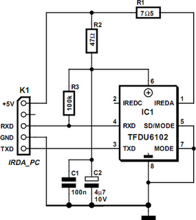
As can readily be seen from the schematic diagram, this doesn`t exactly involve a large array of ICs. This is because transceiver ICs are available for the IrDA standard, so only a few passive components have to be added to obtain an operational circuit. The author has successfully built this circuit many times using the TFDU5102 from Vishay Semiconductors (formerly Telefunken).
If this IrDA transceiver is no longer available (it has been officially discontinued), the largely pin- and function-compatible TFDU6102 can be used without any problems. This IC is faster and meets the latest IrDA specication. The TFDU6102 low-power receiver IC supports IrDA at data rates up to 4 Mbit/s (FIR), HP-SIR, Sharp ASK, and carrier-based remote control modes up to 2 MHz.
The IC contains a photodiode, an infrared emitter and CMOS control logic. The IC also has internal protection against electromagnetic immissions and emissions, so no external screening is necessary. The IC works with a supply voltage of 2. 7 5. 5 V, so it is suitable for use in desktop PCs, notebooks, palmtops, and PDAs. It is also used in digital still and video cameras, printers, fax machines, copiers, projectors, and many other types of equipment.
The author has designed a printed circuit board for the IrDA module that is only 20 G— 20 mm square. Of course, this means that all of the components are SMD types. The TFDU6102 in the babyface` package is available in upright and‚at versions. Here the upright version (suffix TR3`) is used. Thanks to its small size, the assembled circuit board can easily be placed behind a drive bay cover or the like. It is connected to the motherboard by ave-way‚at cable. The pin assignments for header X1 must match the mating connector on the motherboard. After you have fitted the module, you may have to edit the BIOS settings to activate the UART for IrDA operation.
These settings enable the (Windows) operating system to boot the new device and automatically install it. You may have to brie‚y insert the Windows CD to modify the settings. There is an abundance of free programs on the Internet that use the IrDA interface. 🔗 External reference
Related Circuits
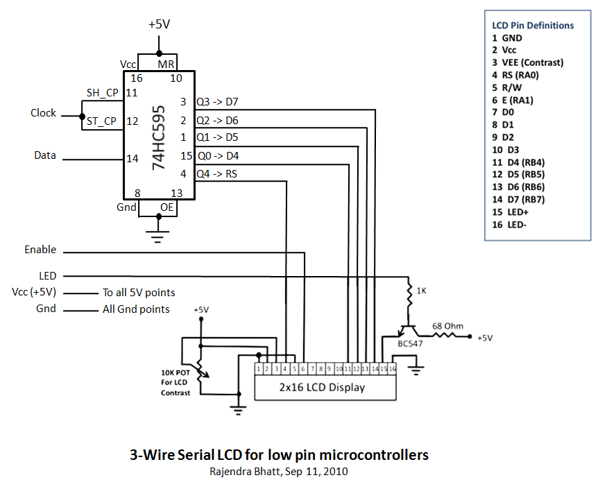
Library routines for a 3-wire LCD interface utilizing the 74HC595 shift register. Additional details can be found in the attached ReadMe document or on the associated webpage. The library routines for the 3-wire LCD interface are designed to facilitate communication...

This is a design of the circuit diagram for an RS422 interface. Connector K1 is connected to the serial port of the PC, and power for the PC side of the circuit is obtained from the signal lines DTR...
As shown in the figure, D187 is a UART with its RX/TX signals connected through optocouplers N21, N22, and N29, providing complete optoelectronic isolation for the RS-485 communication interface receiver/transmitter D28 and microprocessor D211. D197 serves as a generator,...
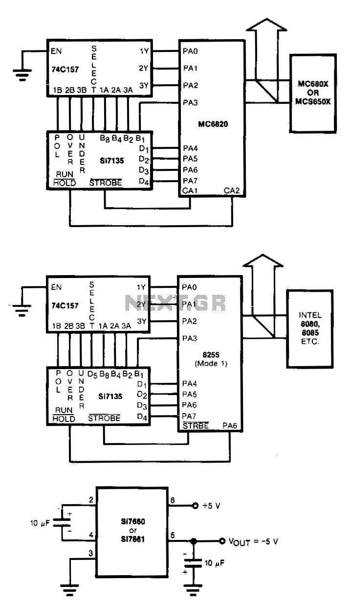
Circuits to interlace the Si7135 directly with two popular microprocessors are shown in Figs. 18-2a and b. The 8080/8048 and the MC6800 families with 8-bit words need to have polarity, overrange, and underrange multiplexed onto the digit 5 word....
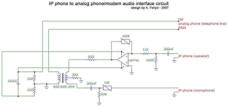
The transformer is a 600:600 ohm transformer, also referred to as a 1:1 ratio 600 ohm transformer. It has approximately the same number of turns on both the primary and secondary coils and is optimized for operation at a...
Many microcontroller designs typically integrate various interfacing methods. A microcontroller (µC) system can be viewed as a system that reads from inputs. Microcontroller systems are versatile platforms that facilitate the integration of multiple interfacing methods to interact with various peripherals...
Warning: include(partials/cookie-banner.php): Failed to open stream: Permission denied in /var/www/html/nextgr/view-circuit.php on line 713
Warning: include(): Failed opening 'partials/cookie-banner.php' for inclusion (include_path='.:/usr/share/php') in /var/www/html/nextgr/view-circuit.php on line 713