
Sequence timer circuit diagram of 555 chips
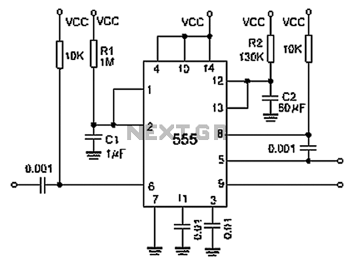
The described circuit utilizes a 556 timer IC, which consists of two independent timer circuits capable of operating in monostable or astable modes. In this configuration, the first half of the 556 timer generates a pulse that is coupled to the second half through a 0.001 F capacitor. This capacitor serves to isolate the two stages while allowing the timing pulse to pass, effectively enabling the second timer to start its operation based on the output from the first.
The timing of the first half is determined by the resistor R1 and capacitor C1, where the delay time (T1) can be calculated using the formula T1 = 1.1 * R1 * C1. This establishes the duration of the output pulse from the first timer stage. The output pulse can trigger the second timer stage, which is similarly configured with resistor R2 and capacitor C2. The timing for the second stage (T2) is given by T2 = 1.1 * R2 * C2, which determines how long the output from the second timer remains active.
The mention of a "6-foot ground" likely refers to the grounding technique used in the circuit layout, ensuring a common reference point for the timer circuits. This grounding is crucial for the reliable operation of the timers, as it minimizes noise and potential interference that could affect timing accuracy.
In summary, this circuit effectively demonstrates the use of a 556 timer IC in a cascading configuration, allowing for precise timing control through the careful selection of resistors and capacitors, while the coupling capacitor facilitates communication between the two timer stages. Proper design considerations should be taken into account to ensure that the values of R1, R2, C1, and C2 are chosen to meet the specific timing requirements of the application. By 0.001 F the first half of the coupling capacitor 556 pairs timer output is supplied to the second half of the input given individual delay equal to the sum of the total dela y. The 6 foot ground can instantly start the first half of the timer. After the interval determined by the 1.1R1C1 second start delay timer, the value depends on the 1.1R2C2.
Related Circuits
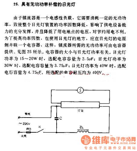
The fluorescent lamp with reactive power compensation operates with a ballast that acts as an inductive load. This inductive load requires reactive power, which leads to a decrease in the power factor of the fluorescent lamp. A lower power...
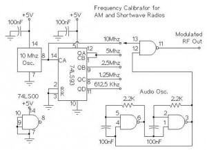
The following circuit illustrates an AM/Shortwave Radio Frequency Calibrator Circuit Diagram. This circuit is based on the 74LS93 IC. Features: The .. The AM/Shortwave Radio Frequency Calibrator Circuit utilizes the 74LS93 integrated circuit, which is a 4-bit binary counter. This...
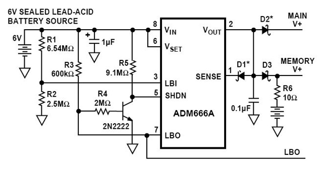
This is a circuit diagram for a solid-state charge detector. It can detect very weak electric fields. The circuit has three components: a 6-volt battery, a light-emitting diode (LED), and a field-effect IC ADM666A. The solid-state charge detector circuit is...
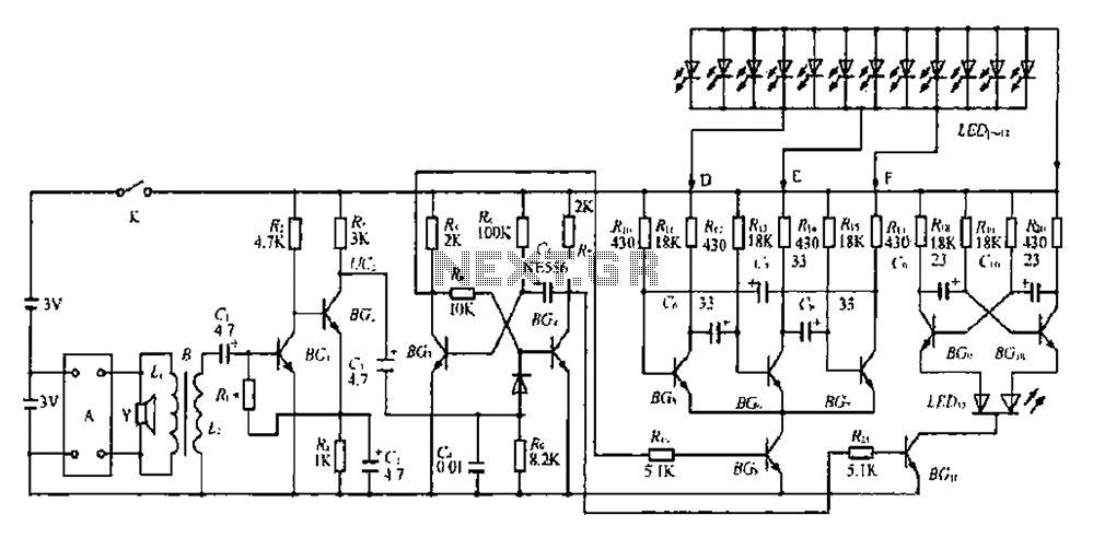
The BGl and BG2 form a directly coupled amplifier, while BG and BG4 consist of a monostable trigger circuit. Without receiving a prior trigger signal, BG3 enters a saturated conduction state. During this steady state, the collector of BG4...
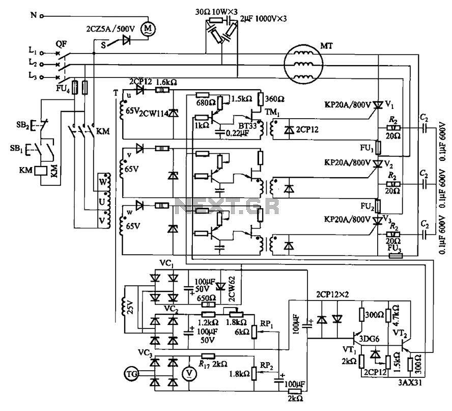
The circuit depicted in Figure 3-181 comprises three thyristors, labeled V1 to V3. The trigger circuit utilizes a single-junction transistor relaxation oscillator. The speed control circuit incorporates negative feedback. A master adjust potentiometer, designated as RPi, is used to...
PWM waveforms are frequently employed to regulate the speed of DC motors. The mark/space ratio of the digital waveform can be established either by utilizing an adjustable analog voltage level (as seen in a NE555-based PWM generator) or through...