
Power loss detector
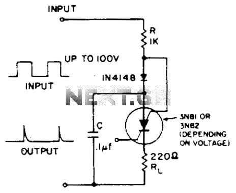
The described circuit utilizes a silicon-controlled switch (SCS) as a key component for controlling the discharge of capacitor C. In the initial state, when a positive voltage is applied to the input, the current flows through the IN4148 diode, which is configured to allow current flow in one direction only. This charging action of capacitor C through resistor R establishes a voltage across C, while the SCS remains in its non-conductive state due to the blocking action of the diode.
When the input transitions to a negative voltage, it provides the necessary anode-gate current to the SCS, effectively triggering its conduction state. This transition allows capacitor C to discharge its stored energy through resistor R1. The discharge path is crucial for controlling the timing and duration of the output signal, which can be utilized in various applications, including timing circuits, pulse generation, and signal modulation.
The choice of components, such as the IN4148 diode, is significant due to its fast switching capabilities and low forward voltage drop, which enhances the efficiency of the circuit. Additionally, the values of resistors R and R1, along with the capacitance of C, must be carefully selected to achieve the desired timing characteristics and ensure stable operation within the specified voltage and current ranges.
Overall, the circuit effectively demonstrates the interaction between input signals and the control of energy storage and release via the SCS, providing a reliable mechanism for electronic control applications.A positive going input charges C through the IN4148 and R. The diode keeps the scs off. A negative going input supplies anode-gate current triggering on the scs discharging C through Rl. 🔗 External reference
Related Circuits
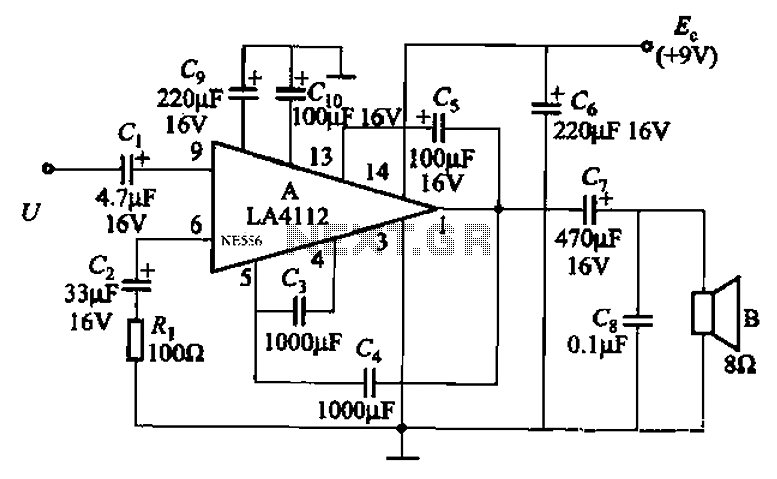
Audio power amplifier circuit utilizing the LA4112 integrated power amplifier along with additional components as shown in the figure. The audio power amplifier circuit based on the LA4112 integrated power amplifier is designed to deliver high-quality audio amplification for various...
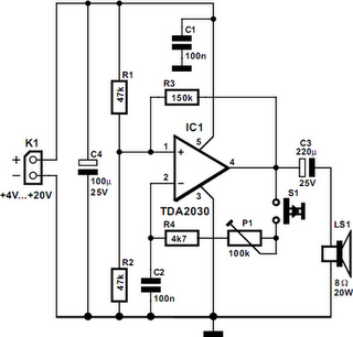
A powerful buzzer in the room, combined with a pushbutton at the bottom of the stairs or in the kitchen, could be very useful in such situations. The core of this circuit is formed by IC1, a TDA2030. This...
This chapter presents a variety of circuits for basic power supplies, including both line-powered and inverter types, some of which feature regulators, modulation inputs, and additional functionalities. Several circuits have been reverse-engineered from actual commercial products, and others, designed...
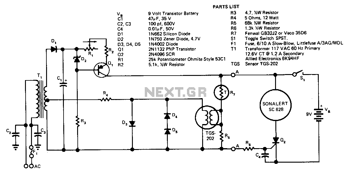
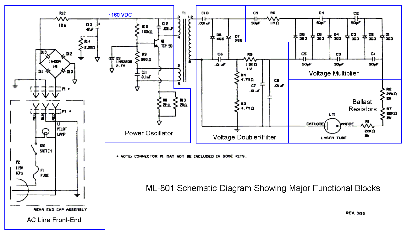
Transformer T1 provides power to the sensor's heater. Due to the sensor's high sensitivity to heater voltage, diodes D1, D4, and D5 regulate this voltage. T1, in conjunction with D1 and C2, forms a DC power supply, with current...
The TEM, specifically the Jeol 2000fx model, is equipped with two additional detectors: a secondary electron detector for SEM imaging and a STEM detector located at the bottom of the microscope. As the system dates back to the 1980s,...
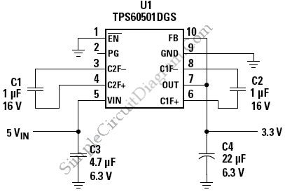
This is a circuit of a step-down charge pump regulator for USB-powered devices. The critical design parameter of this circuit is the circuit area. The step-down charge pump regulator is designed to efficiently convert a higher input voltage from...