
20W Stereo Amplifier Circuit
The design of the 20-W + 20-W stereo amplifier employs a bridge configuration to maximize output power while maintaining efficiency. The voltage divider formed by resistors R1 and R2 is crucial for managing the input signal level, ensuring that the subsequent amplification stages operate within their optimal range. The use of potentiometer P1 allows for adjustable gain, providing flexibility based on the input signal characteristics and desired output levels.
Capacitors C1 and C2 serve the dual purpose of DC blocking and AC coupling, facilitating the transfer of the audio signal while preventing DC offset from affecting the amplifiers. The bridge configuration of amplifiers A and B within IC1 allows for differential amplification, which enhances the output power delivered to the speakers. The outputs from pins 10 and 8 are designed to drive the speaker load directly, thus eliminating the need for a common ground connection, which is critical for preventing potential ground loop issues that could introduce noise into the audio signal.
Resistors R6 and R7 are strategically selected to set the gain of the amplifiers, allowing for fine-tuning of the overall amplification factor. The frequency stability is ensured by resistors R9 and R10 in conjunction with capacitors C9 and C10, which form a feedback network that mitigates the risk of oscillation, thereby enhancing the reliability of the amplifier under varying load conditions.
The bootstrapping effect provided by capacitors C6 and C7 is particularly important for maintaining linearity at low frequencies, which is essential for high-fidelity audio reproduction. The inclusion of LED L1 serves as a visual indicator of power status, enhancing user experience by providing immediate feedback when the amplifier is operational.
Power protection is a critical aspect of this design, with diode D1 safeguarding the amplifiers from reverse polarity conditions that could lead to damage. The additional filtering provided by capacitor C11 ensures that the power supply remains stable and free from high-frequency noise, which could otherwise affect the performance of the amplifier.
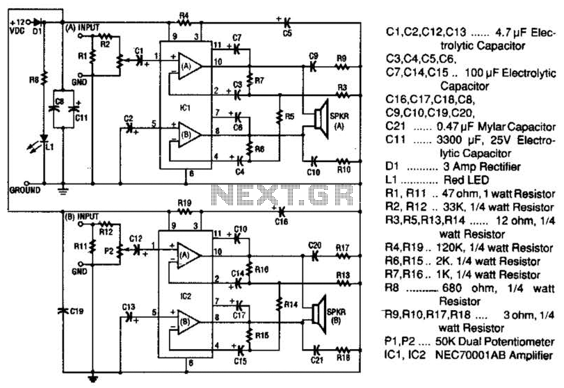
Overall, this 20-W + 20-W stereo amplifier is engineered to deliver robust audio performance while maintaining efficiency and reliability across its operational range. The thoughtful selection of components and their configuration contributes to a high-quality audio experience suitable for various applications. The 20-W + 20-W stereo amp consists of two complete, separate 20-W RMS bridge-type amplifiers. The input signal source is brought into the amplifier through the voltage divider network, which is made up of Rl, R2, and PI. Resistor Rl provides a load impedance between the signal source and ground. Resistor R2 couples that signal to potentiometer PI.The signal is coupled by capacitor CI to the noninverting (+) input (pin 1) of internal amplifier (A) of IC1, where the signal is greatly amplified.
Capacitor C2 couples the (+) input of the other (B) internal amplifier of IC1 to ground. That causes the input signal, which is referenced to ground, to be coupled to both amplifiers because both the inputs and outputs of IC1 (A) and IC1 (B) are connected in a bridge configuration. Notice that the output of IC1 (A) from pin 10 is connected to one side of the speaker and the output of IC1 (B) from pin 8 is connected to the other side of the speaker.
That is why the speakers used cannot have one side connected to ground. Resistors R6 and R7 set the gain of the amplifier. Resistors R9 and R10 and capacitors C9 and C10 provide frequency stability and prevent oscillation. Capacitors C6 and C7 provide bootstrapping, which prevents distortion at low frequencies. LED LI lights up by way of a series resistor connected from the anode to +12 Vdc when power is applied.Power for both IC1 and IC2 is brought in through D1 (to protect amplifiers from reverse polarity). Capacitor Cll provides additional power supply line filtering. This booster is capable of producing 20 W RMS output out of each channel. 🔗 External reference
Related Circuits
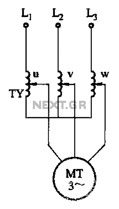
The circuit depicted in Figure 3-176 illustrates an adjustment method that allows the motor to operate at equilibrium. The adjustment range is relatively wide; however, it necessitates a three-phase voltage regulator, which incurs higher input costs. The circuit design in...
Engineer Radu Preda from Romania has developed two energy-saving lighting circuits designed to control the duration that lights are activated, ultimately aiming to reduce electricity expenses. The first circuit utilizes a relay, while the second employs an optoisolator triac...
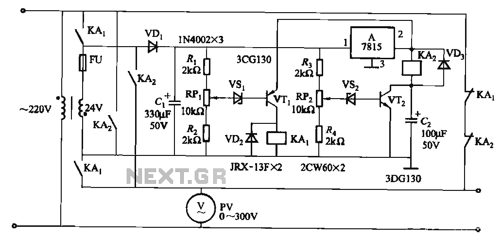
When the input voltage is in the range of 170-260V AC, the output AC voltage falls between 187-231V. The transformer ratio is k = 24/220 = 0.11. If the input voltage drops below 170V, relay KAi activates (adjusted by...
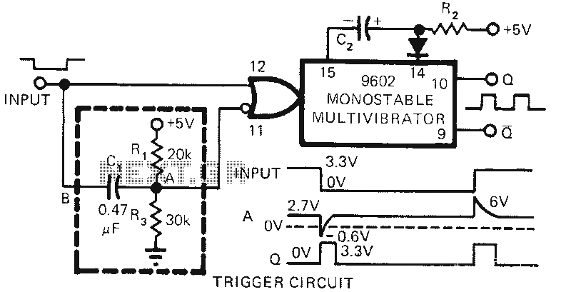
The 9602 multivibrator circuit can trigger either the rising edge or the falling edge of a square wave, but not both simultaneously. To enable double-edge triggering, two additional resistors and a capacitor can be employed. When the input signal...
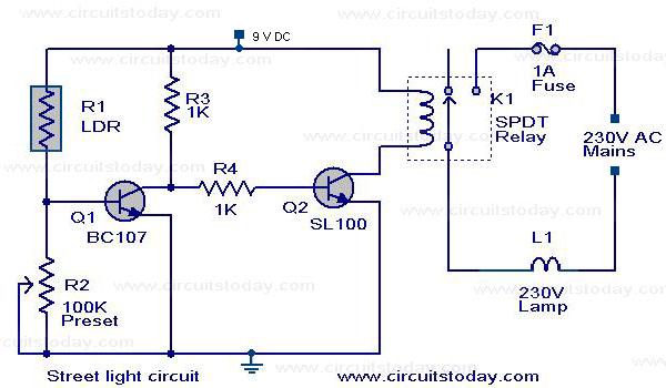
A street light that automatically switches ON when night falls and turns OFF when the sun rises. The circuit uses an LDR to sense the light. The automatic street light circuit functions by utilizing a Light Dependent Resistor (LDR) as...
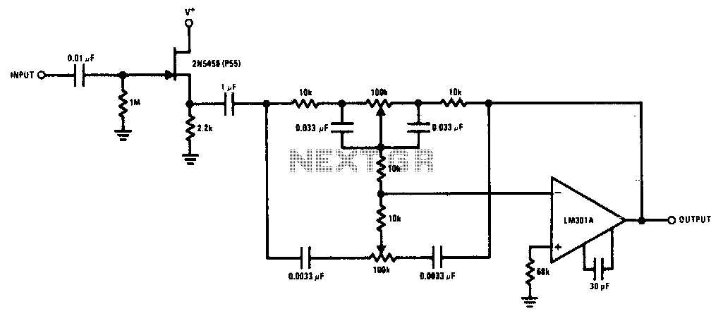
The 2N5458 JFET offers high input impedance and low noise characteristics, making it suitable for buffering an operational amplifier feedback tone control circuit. The 2N5458 is a Junction Field Effect Transistor (JFET) known for its superior electrical characteristics, particularly in...