
USB RGB LED VU Meter
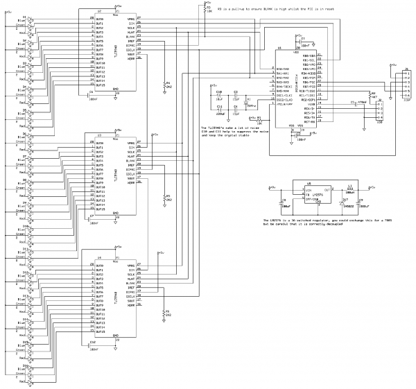
The RGB LED VU Meter project effectively integrates hardware and software components to create a dynamic audio visualization tool. The use of the PIC18F2550 microcontroller as the main control unit allows for efficient USB communication and LED control. The TLC5940 LED drivers are pivotal in managing the brightness levels of the LEDs, with their capability to handle PWM enabling a smooth transition between different brightness states. The decision to use direct control for the LEDs enhances the visual output, providing a clear and vibrant display that responds to audio signals in real-time.
In terms of implementation, the circuit design emphasizes stability and performance. The inclusion of large capacitors near the crystal oscillator is crucial for mitigating power fluctuations that could disrupt the microcontroller's operation. This design choice is particularly important given the high-frequency switching required by the TLC5940s, which can introduce significant noise into the power supply lines. The cascading of multiple TLC5940 chips is a strategic choice to expand the number of controllable LEDs, allowing for a complex and colorful display while maintaining a manageable level of complexity in the firmware.
The software architecture is well-structured, utilizing an open-source framework to facilitate USB HID communication. This approach not only enhances compatibility with various systems but also encourages community contributions and improvements. The core audio API integration allows for advanced audio processing capabilities, such as track information retrieval and audio control surface implementation, making the VU Meter not only a visual tool but also a platform for further audio-related projects.
Overall, the RGB LED VU Meter project stands as a comprehensive example of integrating microcontroller technology with audio processing to create an engaging visual display, suitable for both hobbyists and professionals interested in LED control and audio visualization.This project creates a RGB LED VU Meter which is controlled via USB by a Windows 7 or Vista host machine. The project serves several purposes: Firstly, it demonstrates how to read audio information from the Windows machine and pass this over USB to the device (which is a question which popped up several times after my USB Performance Monitor proje
ct). Secondly, it implements an open source TLC5940 driver. Although a library has been available for the AVR microcontroller, I wasn`t able to find an open source library for the PIC. Hopefully this demonstration will be useful to anyone wanting to control a large number of LEDs with PWM brightness control.
The hardware in this project is very straight forward. The demonstration board consists of a 5V regulator (switching), a PIC18F2550 with the required USB components, 3xTLC5940 16 channel serial LED drivers with PWM and 16 high intensity RGB LEDs. The only real thing of `note` in the circuit design is the two large capacitors placed next to the crystal oscillator.
The high-speed switching performed by the 5940s when controlling the LEDs via PWM generates a lot of power-rail noise (and I mean a lot!). The two capacitors help to ensure that the PIC`s timing circuitry remains stable. During breadboarding the 5940s would cause the PIC to reset as well as other nasty side-effects. As I wanted to test and demonstrate cascaded TLC5940s the LEDs are not multiplexed. Each LED is under direct control. However, given the big amount of brightness generated by the LEDs the end result would not suffer due to multiplexing and the code can be readily adapted if required.
The firmware is based on the software available from my Open Source Framework for USB Generic HID devices based on the PIC18F and Windows. I`ve added two layers to this base, the lowest level is a generic TLC5940 driver library. The TLC5940 is a 16 channel LED driver which supports both 4096 brightness levels (using PWM) and has independent brightness level correction for each LED.
The driver can support a single TLC5940 chip, or you can cascade them together. Theroetically you should be able to control around 20xTLC5940s from a single PIC (meaning you would have 16x20 = 320 LEDs in total). Although I haven`t tested it up to that maximum, this example project uses 3 chips cascaded to provide the 48 channels required for the 16 RGB LEDs.
Layered over the TLC5940 is another library which implements RGB control via the 5940 library. This includes fade on, fade off, colour balancing and a number of other useful functions to make controlling the LEDs easy. USB control is provided by two commands, the first command allows the host to specify the colour intensities of all 16 LEDs using `standard` 0-255 values for the red, green and blue channels.
The second command allows the host to specify the required fade-out time for the LEDs (the libraries support fade-on also, however this is not required by the VU meter demonstration). The host software is written using Visual Studio C# 2010 and is compatible with both Windows 7 and Vista.
Due to the fact it uses the core audio API it will not work on Windows XP (simply because XP doesn`t supply the API). The host software is made up of 3 parts. My open source C# library performs the USB generic HID communication. The core audio API is provided by Ray Molenkamp who published the API wrapper over on The Code Project.
The API is really very powerful, you can even use it to grab the track information and display it on an LCD, or implement USB audio control surfaces. The final part of the host software is the VU Meter display code itself. As you can see from the screenshot there are a number of options available. You can set the `damping` time of the display (the rate at which it drops to follow the audio - slower damping makes the display smoother but at the cost of accuracy).
The fade-off time configures the time it takes for the LEDs 🔗 External reference
Related Circuits
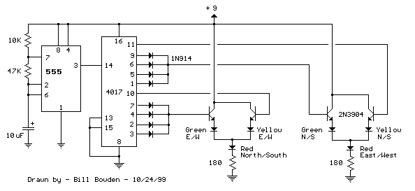
The LED traffic Light circuit controls 6 LEDs (red, yellow and green) for both north/south directions and east/west directions. The timing sequence is generated using a CMOS 4017 decade counter and a 555 timer. Counter outputs 1 through 4...
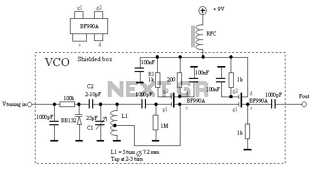
The VCO is based on a Hartley oscillator. The frequency is determined by L1 and capacitor C1. The tuning voltage will change the capacitance in the varactor BB132 which will change the oscillation frequency. The value of capacitor C2...
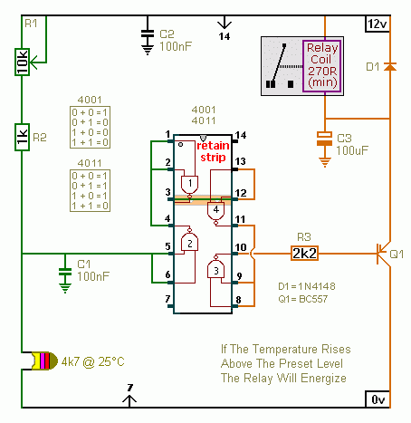
A CMOS 4001 or a CMOS 4011 can be utilized in this circuit, as both contain four two-input gates. The inputs of each gate are connected together, allowing them to function as simple inverters. This means that when both...
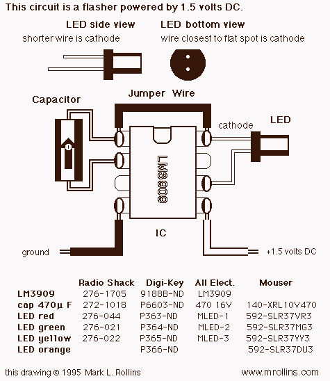
This project uses a 3909 IC and a few other parts; power is 1.5 volts DC. The project employs the 3909 integrated circuit (IC), which is a versatile component commonly used in various electronic applications, particularly in timer and oscillator...
Blinking an LED is the introductory project for programming microcontrollers. It serves as an effective method to navigate the entire development process and verify the functionality of all tools. This chapter involves connecting a light-emitting diode (LED) to an...

This Outdoor LED Solar Garden Lights project is a hobby circuit for an automatic garden light that utilizes a light-dependent resistor (LDR) and a 6V/5W solar panel. During daytime, the internal rechargeable 6 Volt sealed lead-acid (SLA) battery is...
Warning: include(partials/cookie-banner.php): Failed to open stream: Permission denied in /var/www/html/nextgr/view-circuit.php on line 713
Warning: include(): Failed opening 'partials/cookie-banner.php' for inclusion (include_path='.:/usr/share/php') in /var/www/html/nextgr/view-circuit.php on line 713