
LED Traffic Lights for Games with 555
The LED traffic light circuit is designed to manage the operation of six LEDs, specifically red, yellow, and green, for two directional flows: north/south and east/west. The core of this circuit utilizes a CMOS 4017 decade counter, which provides a sequential output to control the LEDs based on a timing sequence generated by a 555 timer configured in astable mode.
In operation, the first four outputs of the 4017 counter (Q0 to Q3) are utilized to control the red LED for the north/south direction and the green LED for the east/west direction. This is achieved by wire ORing these outputs through four 1N914 diodes, which allows for the simultaneous illumination of the respective LEDs during the first four counts.
At the fifth count (pin 10), the circuit activates both the yellow LED for the east/west direction and the red LED for the north/south direction, signaling a transition phase. The subsequent counts from six to nine are similarly wire ORed to control the red LED for the east/west direction and the green LED for the north/south direction, ensuring that traffic flow is efficiently managed.
On the tenth count (pin 11), the circuit again illuminates the red LED for the east/west direction while activating the yellow LED for the north/south direction, indicating that a change in traffic signals is imminent.
The timing for the red and green LEDs is designed to be four times longer than that for the yellow LEDs, which is critical for ensuring safe transitions for vehicles and pedestrians. The complete cycle time can be adjusted via a 47K ohm resistor, allowing flexibility in the timing parameters based on traffic conditions or regulatory requirements.
For those looking to enhance the circuit's efficiency, the eight 1N914 diodes used for wire ORing can be replaced with a dual 4-input OR gate, such as the CD4072, which can simplify the design and reduce the component count while maintaining functionality. This modification could also improve reliability and reduce potential points of failure in the circuit.The LED traffic Light circuit controls 6 LEDs (red, yellow and green) for both north/south directions and east/west directions. The timing sequence is generated using a CMOS 4017 decade counter and a 555 timer. Counter outputs 1 through 4 are wire ORed using 4 diodes so that the (Red - North/South) and (Green - East/West) LEDs will be on during the first four counts.
The fifth count (pin 10) illuminates (Yellow - East/West) and (Red - North/South). Counts 6 through 9 are also wire ORed using diodes to control (Red - East/West) and (Green - North/South). Count 10 (pin 11) controls (Red - East/West) and (Yellow - North/South). The time period for the red and green lamps will be 4 times longer than for the yellow and the complete cycle time can be adjusted with the 47K resistor.
The eight 1N914 diodes could be subsituted with a dual 4 input OR gate (CD4072). 🔗 External reference
Related Circuits
LEDs provide a convenient way to electronically display information. Although the seven-segment LED display, arranged in the form of the digit 8, is common. The seven-segment LED display is a widely used electronic component for visual representation of numerical information....

A few days ago, the rear light burned out. While it is not critical, the front light is essential for nighttime visibility. The reflective red plastic at the back provides some safety, so there is no immediate concern. Nonetheless,...
This circuit triggers an alarm when its LDR (Light Dependent Resistor) sensor is exposed to light from the sun or a lamp. A 555 astable multivibrator is utilized to generate a tone of approximately 1 kHz upon detecting light....
The circuit illustrated in Figure 2-50 utilizes a field effect tube and a combination of electronic components to create a unique self-lighting controller. The working lamp remains illuminated at a reduced brightness rather than being completely turned off, which...
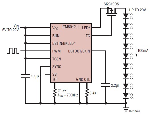
The LTM8042 integrates a boost power topology with a unique current loop to function as a constant-current source. The PWM input allows for LED dimming ratios of up to 3000:1, while analog dimming can be achieved with a single...
This is a very simple circuit utilizing a 555 timer IC to generate a square wave of frequency that can be adjusted by a potentiometer. With values given, the frequency can be adjusted from a few Hz to several...