
Second-Order Polynomial Generator Circuit
The circuit design revolves around the use of an analog multiplier, which serves as the core component for generating the quadratic output. The analog multiplier's functionality allows it to multiply two input voltages, effectively enabling the creation of the square term necessary for the second-order polynomial. The precision resistors play a crucial role in defining the coefficients of the polynomial, ensuring accurate scaling and adjustment of the output voltage.
The input signal, represented by Vr, is processed through a voltage-divider network composed of resistors R3 and R4. This network is essential for managing the input signal's amplitude and adjusting the coefficient (c) associated with the square term. By altering the resistor values, the attenuation can be finely tuned, allowing for precise control over the polynomial's characteristics.
In addition to the square term, the circuit includes a passive adder formed by resistors R1, R2, and R0. This configuration connects to the internal summing circuit of the analog multiplier, enabling the generation of the remaining two polynomial terms: the linear coefficient (b) and the constant offset term (a). The passive adder effectively combines these terms, ensuring that the output voltage accurately reflects the desired second-order polynomial.
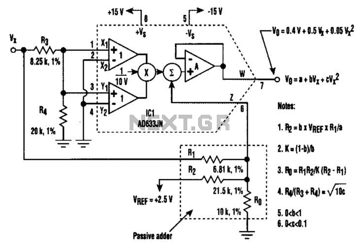
Overall, this circuit provides a versatile and precise means of generating second-order polynomial outputs, utilizing a combination of an analog multiplier and carefully selected resistors to achieve the desired electrical characteristics. The design is well-suited for applications requiring polynomial signal generation and can be adapted for various input signal conditions by adjusting the resistor values accordingly. By using a circuit built with a single analog multiplier and five precision resistors, an output voltage (Ko) can be made to create a second- order polynomial. The circuit implements the quadratic shown. The input terminals of IC1 are connected to create a positive square term and present the Vr signal to the output with a 1-10-V scale factor.
Incorporating the voltage-divider network (resistors R3 and R4) in the input signal path provides additional attenuation adjustment for the coefficient (c) of the square term in the quadratic. Then, the passive adder (resistors Rl, R2, and Ro) is wired to ICl`s internal summing circuit to generate the polynomial`s other two terms; the offset term (a) and the linear coefficient (b). 🔗 External reference
Related Circuits
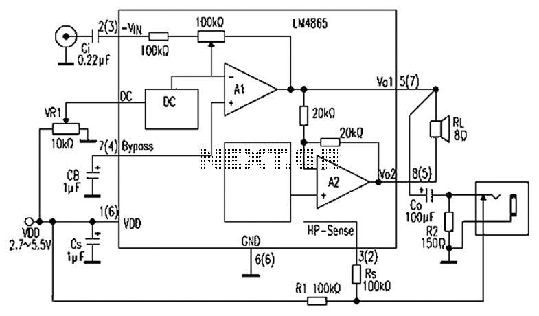
A 750mW bridge-tied load audio amplifier circuit utilizing the LM4065 amplifier is presented below. The LM4865 is available in an 8-pin SO package and an 8-pin mini SMD package. The power supply voltage (VDD) ranges from 2.7V to 5.5V,...
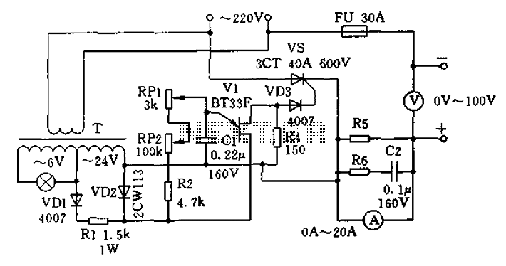
The charging apparatus depicted in the schematic circuit has a maximum output current of 20A and a maximum charging voltage of 80V. It can be adjusted starting from 0V, making it suitable for charging various types of batteries. The...
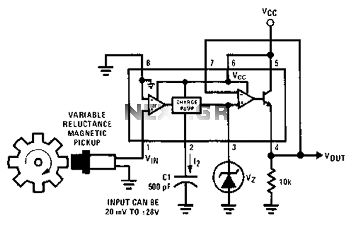
After each zero electromagnetic pickup receives a sine wave input, as illustrated in the National Semiconductor LM2907 circuit, it generates an output pulse. This circuit can be utilized in digital control systems. The width of each pulse corresponds to...

The circuit activates a light corresponding to the first button pressed in a "Who's First" game. Three stages are illustrated, but the circuit can be expanded to accommodate any number of buttons and lamps. The described circuit operates as a...
This circuit features a portable solid-state bright light utilizing the LT1932 integrated circuit. It can be powered by two AA dry or rechargeable pen-light batteries. The design allows for customization of the housing, enabling various applications such as a...

To ensure proper operation of the transistor in a circuit, it is essential to measure the reverse breakdown voltage of the transistor. This is particularly important for tubes with high reverse breakdown voltage requirements, such as those used in...