
use CD-ROM drive as stand-alone audio CD player

The D-connector, commonly utilized in various electronic applications, serves as a reliable interface for power and signal transmission. In this specific configuration, the 12V supply is indicated by the yellow wire, which must be connected to the designated pin on the right side of the connector. This orientation is crucial for ensuring proper functionality and preventing potential damage to connected devices.
The D-connector typically features multiple pins arranged in a specific layout, allowing for various configurations depending on the application. In this case, the correct connection of the yellow wire to the right pin is essential for the proper operation of the circuit. It is recommended to verify the pinout diagram specific to the D-connector being used, as different models may have varying pin assignments.
Moreover, attention should be paid to the overall wiring practices, including the use of appropriate gauge wire to handle the current load, secure connections to prevent intermittent faults, and proper insulation to avoid short circuits. It is also advisable to perform a continuity test post-assembly to ensure that the connections are intact and functioning as intended before powering the circuit.
Additionally, any modifications or alterations to the circuit should be approached with caution, and it is advisable to consult relevant documentation or seek expert guidance when necessary to avoid compromising the integrity of the electronic system.Ensure that the 12V(yellow) wire is connected to the right of the D-connector(as seen from behind, i. e the connector holes away from you with the curved portion of the connector upwards) Disclaimer: All the information present on this site are for personal use only.
No commercial use is permitted without the prior permission from authors of this w ebsite. All content on this site is provided as is and without any guarantee on any kind, implied or otherwise. We cannot be held responsible for any errors, omissions, or damages arising out of use of information available on this web site.
The content in this site may contain COPYRIGHTED information and should not be reproduced in any way without prior permission from the authors. 🔗 External reference
Related Circuits
This audio peak detector enables monitoring of a pair of stereo channels using a single LED indicator. The circuit employs identical configurations for both left and right channels. It utilizes the switching levels of Schmitt trigger NAND gates within...
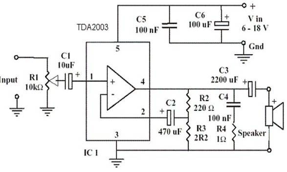
An amplifier device accepts a varying input signal and produces an output signal that varies in the same manner as the input but with a larger amplitude. The input signal can be a current, voltage, mechanical motion, or any...
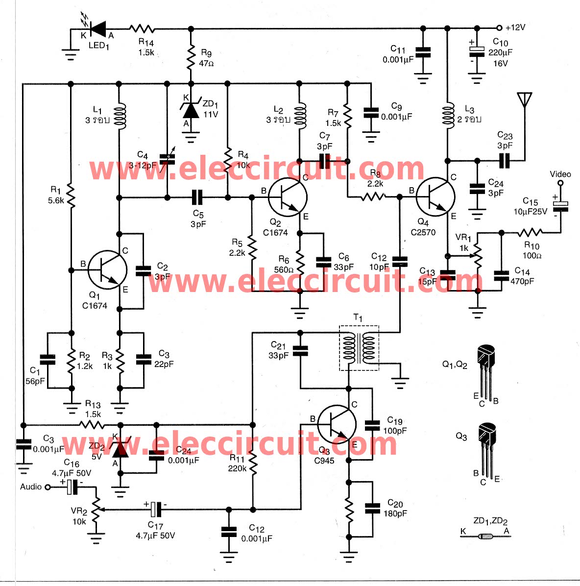
To transmit video and audio signals to multiple televisions simultaneously, a video amplifier splitter utilizing a transistor can be employed. A video amplifier splitter is an electronic device designed to distribute a single video and audio signal to multiple output...
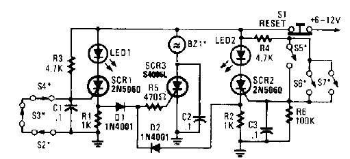
A straightforward high-power alarm driver electronic project can be developed using this circuit diagram. This high-power alarm driver project utilizes a low-power SCR to trigger a high-power SCR. When switches S2, S3, or S4 are opened or switches S5,...
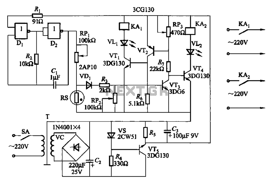
Two NAND gates (Di, Dz) and a resistor (Rz) along with capacitors (C1, etc.) form an RC self-excited multivibrator with an oscillation frequency of 2.5 Hz and an oscillation amplitude of 4 V. This circuit is used as a...
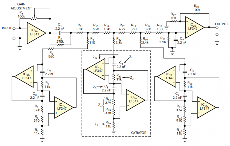
The filter should provide adjustable gain to maximize SNR at the audio processor's first stage. The filter's frequency response should also include a notch at 19 kHz to achieve maximum attenuation at the FM-subcarrier pilot-tone frequency and thus minimize...