
Asymmetric Timer Circuit With 7555 IC
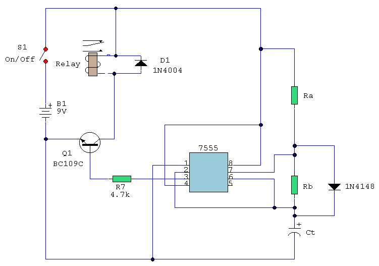
The timer circuit utilizing the 7555 IC operates as an astable multivibrator, which continuously switches between its high and low states without requiring any external triggering. The independent mark and space periods allow for flexible timing applications in various electronic projects.
The timing intervals are determined by external resistors (Ra and Rb) and a timing capacitor (Ct). The calculations for the high and low output durations are crucial for achieving the desired frequency of operation. Specifically, T(on) is influenced by the resistance of Ra and the capacitance of Ct, while T(off) is dependent on Rb and Ct. The factor of 0.7 in the formulas accounts for the charging and discharging characteristics of the capacitor in the circuit.
The discharge path is a critical component of the circuit, ensuring that the timing capacitor discharges properly, allowing for consistent timing intervals. The inclusion of a transistor can provide additional control or amplification of the output signal, depending on the circuit's application.
Powering the circuit with a battery ensures portability and ease of use in various settings. A switch is often included to enable or disable the circuit, providing user control over its operation. The diode serves to protect the circuit from reverse polarity, which can occur if the battery is connected incorrectly.
Overall, this timer circuit offers a versatile solution for generating precise timing sequences in hobbyist projects, educational demonstrations, or prototyping environments. The flexibility in setting independent timing intervals makes it suitable for applications such as LED blinkers, tone generators, or pulse width modulation (PWM) signals.The following circuit shows a timer circuit with independent mark and space periods. This circuit based on the 7555 IC. Features: output high is calculated by T(on) = 0. 7 Ra Ct, output low is calculated by T(off) = 0. 7 Rb Ct, astable timer, (on) and (off) values set independently, discharge path. Component: 7555 IC, Resistor, Transisto r, Battery, Switch, Diode, Capacitor. [hobbyprojects. com] 🔗 External reference
Related Circuits
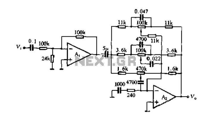
Figure 4-7 illustrates the pitch analysis based on the relationship derived from the design calculation of the control circuit. In this setup, Ai serves as a buffer for the large stage, thereby alleviating the load on the preamplifier output....
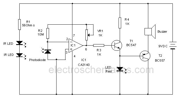
This circuit utilizes invisible infrared light to detect the movement of individuals through a doorway. A brief beep will be emitted when the infrared beam is interrupted. The infrared movement detection circuit employs an infrared LED and a photodiode or...
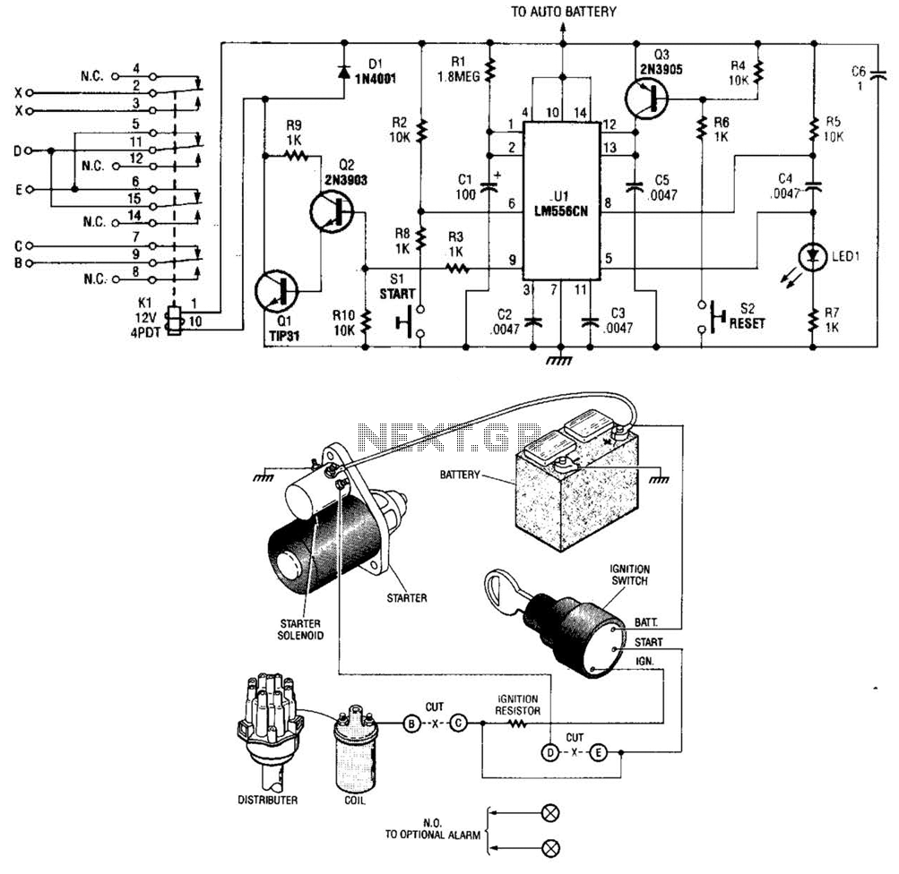
The automobile delayed kill switch operates on a straightforward principle. Upon exiting the vehicle, a hidden pushbutton switch is activated. Although no immediate effect is visible, after a preset duration, a relay engages and locks in place. This action...
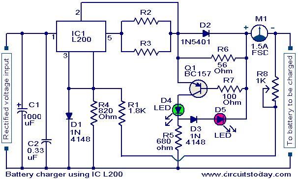
A simple battery charger circuit with reverse polarity indication is presented here. The circuit utilizes the L200 integrated circuit (IC), which is a five-pin variable voltage regulator. The charging circuit can be powered by DC voltage from either a...
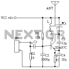
The ordinary triode 3DA87C is utilized to create a long-range FM transmitter circuit, which functions as a standard three-point oscillator circuit. This remote transmitter circuit is capable of large current emissions, achieving a range of up to 1 kilometer...

A simple frequency meter or frequency counter circuit featuring an LCD display and an AVR microcontroller. This includes a DIY schematic circuit diagram and embedded C code. The frequency meter circuit is designed to measure the frequency of input signals...
Warning: include(partials/cookie-banner.php): Failed to open stream: Permission denied in /var/www/html/nextgr/view-circuit.php on line 713
Warning: include(): Failed opening 'partials/cookie-banner.php' for inclusion (include_path='.:/usr/share/php') in /var/www/html/nextgr/view-circuit.php on line 713