
MC14093B Fluid Level SensorCircuit Diagram
The MC14093B is a CMOS quad two-input NAND gate that can be configured to create a fluid level sensor. This circuit typically employs two probes that are placed at different levels in a tank. When the fluid reaches a certain level, it completes a circuit between the probes, allowing the NAND gate to change its output state.
The power supply for the circuit can be derived from a standard DC source, typically ranging from 3V to 15V, depending on the specific application requirements. The output from the NAND gate can be connected to an LED indicator, a relay, or a microcontroller input to signal when the fluid level has reached the designated point.
In addition to the basic functionality, the circuit can be enhanced with additional components such as resistors and capacitors to filter noise and stabilize the output signal. The use of pull-up or pull-down resistors may be necessary to ensure that the NAND gate operates correctly in the desired logic state when the probes are not submerged.
Overall, the MC14093B Fluid Level Sensor Circuit offers a reliable and efficient solution for monitoring fluid levels in various applications, including industrial tanks, water reservoirs, and household appliances. Its simplicity and versatility make it an ideal choice for both hobbyists and professional engineers.The following circuit shows about MC14093B Fluid Level Sensor Circuit Diagram. Features: compact and simple, single-chip circuit, for a wide range .. 🔗 External reference
Related Circuits
An arrangement was established that functions effectively. In the siren circuit, the reed switch was shorted as illustrated. The power supply was removed, and a new configuration was created. The described siren circuit utilizes a reed switch, which is a...
This battery charger circuit is regulated and adjustable, enabling it to charge most NiCAD batteries. It can accommodate both single cells and multiple battery cells connected in series or parallel. The maximum voltage of the batteries should not exceed...
The level control circuit comprises a step-down rectifier circuit, a trigger circuit utilizing two 555 timer ICs (IC1 and IC2), and a relay control circuit. The rectifier circuit is responsible for providing the necessary DC voltage for the flip-flop...
Police siren circuit diagram. This circuit produces a sound similar to a police siren. It utilizes two 555 timer ICs. The police siren circuit typically employs two 555 timer integrated circuits (ICs) configured in astable mode to generate a square...
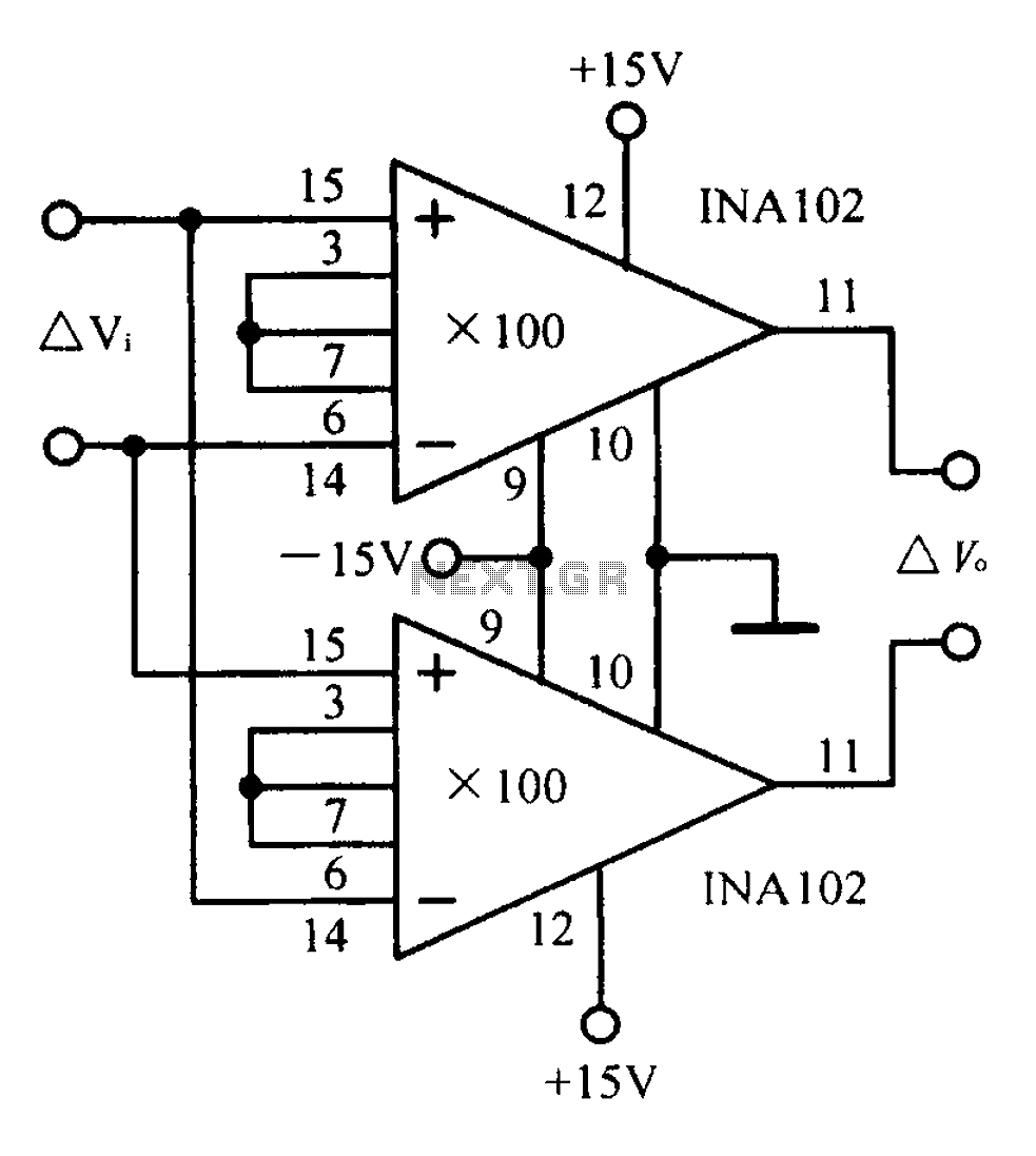
A differential input differential output amplifying circuit diagram. A differential input differential output (DIDO) amplifier is a type of operational amplifier configuration that is designed to amplify the difference between two input signals while rejecting any signals that are common...
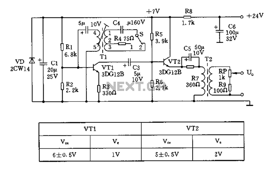
The 450/800Hz oscillation circuit depicted in the figure utilizes transformer coupling. The frequency conversion is achieved by varying the inductance through a variable filter tap (T1). When the switch control signal (S) is set to position 1, the oscillator...