
using LM334Z with soft start
The LM334Z is a versatile current regulator that can be used in various applications requiring constant current output. It is particularly suited for LED driving, biasing transistors, and other applications where stable current is essential. The device operates by maintaining a constant current flow through a load, independent of variations in supply voltage or load resistance.
In this circuit, a 12V battery serves as the primary power source, and the LM334Z regulates the output current to a fixed value of 2mA. The configuration typically involves connecting the LM334Z in a simple circuit with resistors to set the desired current level. The output current can be adjusted by selecting an appropriate resistor value connected to the set pin of the LM334Z.
To ensure optimal performance, it is crucial to consider the power dissipation across the LM334Z, which can be calculated using the formula P = (Vin - Vout) * Iout. In this case, the input voltage is 12V, the output voltage will depend on the load, and the output current is fixed at 2mA. Adequate heat sinking may be required if the power dissipation exceeds the thermal limits of the device.
The LM334Z also features a wide operating voltage range and can handle load voltages up to 40V, making it suitable for various applications beyond simple battery-powered circuits. Additional components, such as bypass capacitors, may be added to the circuit to enhance stability and transient response.
When designing the circuit, it is important to ensure that the LM334Z is connected correctly, with the input voltage applied to the appropriate pins and the output connected to the load. The ground connections must also be secure to prevent erratic behavior. Proper layout and grounding techniques will help minimize noise and improve the overall reliability of the circuit.A bit of a newbie to creating circuits I have a 12V battery regulated to 2mA with an LM334Z current regulator. Here are the docs for the current regulator: .. 🔗 External reference
Related Circuits
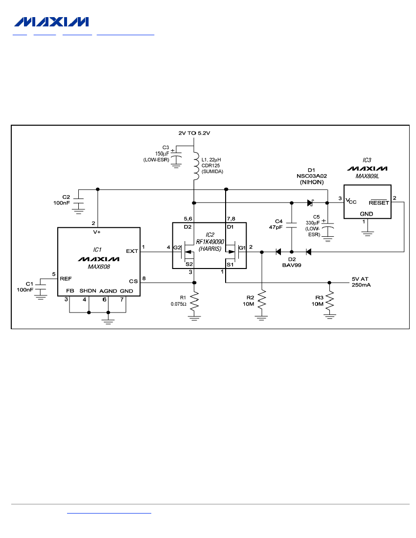
To ensure a full-load start-up, the additional circuitry in this regulated boost converter disconnects the load until the output voltage reaches regulation. Proper operation necessitates a gate-drive voltage adequate to maintain low on-resistance in the switching MOSFET; however, during...
The joystick button inputs can be used as general purpose button or switch inputs, and can also be driven by logic level signals or by open collector or open drain logic outputs. If used with a signal direct from...

By adding the same circuit in parallel, the number of inputs can be increased according to the applications. Each input is connected to the inverting terminal of the LM3900. The built-in amplifier of each section amplifies every audio input...
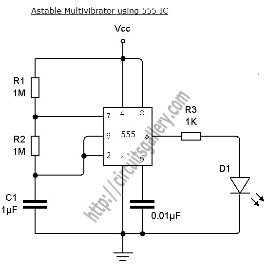
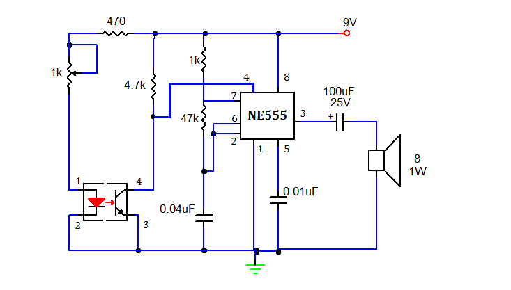
An astable multivibrator can be designed using a 555 timer IC, operational amplifiers, or transistors. The 555 timer IC provides accurate time delays ranging from milliseconds to hours, with the frequency of oscillation adjustable through simple modifications. This is...
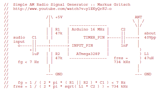
Markus constructed a software AM radio transmitter utilizing an Arduino. The audio signal is supplied to the ADC input via a decoupling capacitor. A PWM output pin directly controls a capacitor-inductor circuit connected to an antenna. The schematic and...
This document presents a simple smoke sensing alarm circuit utilizing a 555 timer. The circuit is designed to detect smoke and trigger an alarm when the air is contaminated. The components employed in this design include an astable multivibrator...