
Astable Multivibrator using NE 555 timer IC
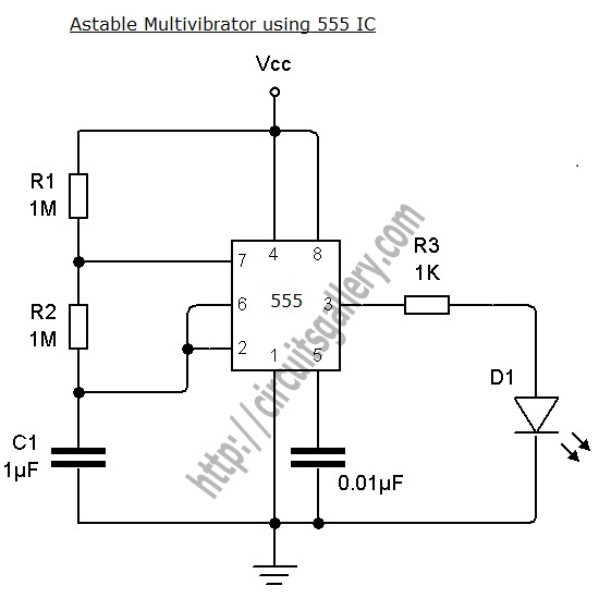
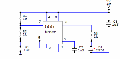
The astable multivibrator circuit based on the 555 timer operates in a continuous oscillation mode, generating a square wave output. The key components include two resistors (R1 and R2) and one capacitor (C1), which determine the frequency and duty cycle of the output waveform. The relationship between these components can be described using the formula for frequency:
\[ f = \frac{1.44}{(R1 + 2R2) \times C1} \]
This formula indicates that increasing the resistance values or the capacitance will decrease the frequency of oscillation. The duty cycle, which defines the proportion of time the output is high versus low, is influenced by the ratio of R1 to R2. For applications requiring specific duty cycles, careful selection of R1 and R2 is essential.
The 555 timer has two comparators internally that compare the voltage across the capacitor with predetermined threshold levels. When the voltage across C1 reaches 1/3 Vcc, the output of the lower comparator goes high, setting the flip-flop. Conversely, when the voltage reaches 2/3 Vcc, the upper comparator output goes high, resetting the flip-flop. This feedback mechanism ensures continuous oscillation.
The reset functionality provided by the fourth pin allows for external control of the timer operation. By applying a low signal to this pin, the timer can be effectively halted, which is useful for applications requiring synchronization or controlled timing sequences. The transistor Q2 acts as a switch, discharging the capacitor and ensuring the circuit can return to its initial state.
This astable multivibrator circuit is widely used in applications such as clock pulses generation, light flashers, tone generation, and frequency modulation. The simplicity of the 555 timer, combined with its versatility, makes it a popular choice for both educational purposes and practical electronic designs.Astable Multivibrator can be designed by using 555 timer IC, Op Amps and also using transistors. The 555 IC provide accurate time delay from mille seconds to hours. The frequency of oscillation can be controlled manually by simple modification. This is a simple 555 timer circuit project. Astable Multivibrator is simply an oscillator circuit that pr oduces continuous pulses. The frequency can be controlled by changing the values of R1, R2 and C1. When the capacitor voltage less than 1/3 Vcc, the lower comparator output will be high, then the control flip flop get set to High. (Q=1, Q`=0, Final output=1). 4th pin is Reset pin, a Low voltage at this pin resets the IC. The Low signal is applied to the base terminal of reset transistor Q2. Then it turns ON followed by Discharge capacitor Q1 and capacitor discharges. See the images below. 🔗 External reference
Related Circuits
Ensure that connections are verified against the circuit diagram and schematic provided below. This can be utilized while following the tutorial video. The circuit diagram serves as a crucial reference for accurately assembling electronic components in a project. It illustrates...
Square wave tone bursts are generated by pressing the pushbutton. The duration of these bursts is determined by how long the voltage at Pin 4 exceeds a specified threshold. The circuit described involves a square wave generator that produces tone...
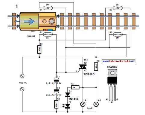
Modern electronics is essential for every large model railroad system, providing solutions to nearly every issue. Although ready-made products are available... Modern model railroad systems rely heavily on advanced electronics to enhance functionality and user experience. These systems often incorporate...
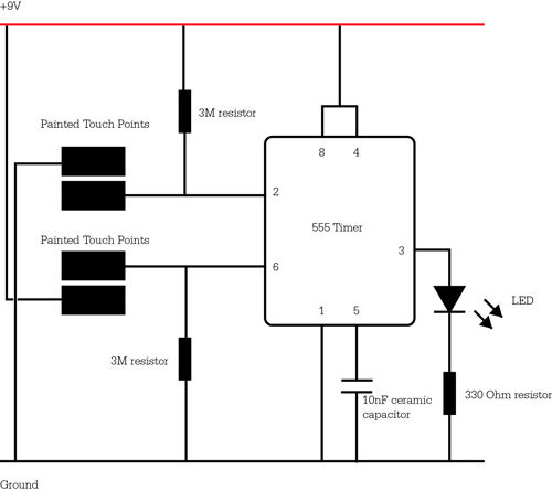
This circuit is built around one of the most popular timer integrated circuits, the 555 timer. It will flash the LED on and off at regular intervals. From left to right, the two resistors and the capacitor set the...
The monostable 555 timer multivibrator circuit, also known as a one-shot monostable multivibrator, functions as a retriggerable pulse generator. The term "monostable" indicates that the circuit has only one stable state, with the unstable state referred to as the...
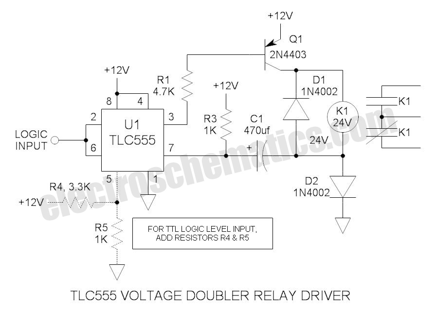
These novel relay driver circuits can activate a relay with a coil voltage rating that is double the Vcc. After activation, the relay armature is held in place. The relay driver circuits described are designed for applications requiring the control...