
Using PicBasic with the PIC16F84 PIC Microcontroller

The project described focuses on utilizing the PicBasic programming language to create a serially controlled I/O expander. The I/O expander serves to enhance the input/output capabilities of microcontrollers, specifically those from the PIC family or the BASIC Stamp. The serin command is employed to facilitate serial communication, allowing for the reception of data from a controlling device.
The circuit typically consists of a PIC microcontroller configured to operate in conjunction with additional I/O pins. The I/O expander can be implemented using a shift register or a dedicated I/O expander IC, which receives serial data and translates it into multiple parallel outputs. This is particularly useful in applications where the number of available I/O pins on the primary microcontroller is limited.
In the implementation, the serin command is utilized to read incoming data. The qualifier feature of the serin command allows for more robust data handling by enabling specific conditions to be set for the incoming serial data. This can include checking for specific start bits or ensuring that data is received in the expected format, thereby enhancing reliability.
The overall design includes pull-up resistors on the input lines to ensure stable logic levels, and decoupling capacitors are placed close to the power pins of the microcontroller to filter out noise. The schematic will typically showcase connections between the microcontroller's serial output pin and the data input of the I/O expander, along with connections for power and ground.
This project exemplifies the ease of programming with PicBasic while demonstrating practical applications for expanding I/O capabilities in embedded systems. The simplicity of using if-then statements in conjunction with the serin command allows for straightforward control logic, making it accessible for both novice and experienced developers.This project uses only a few of the instructions that come with PicBasic, but serves to show how easy PicBasic really is. It also shows how PicBasic strongly resembles programming the BASIC Stamp. Here we are using the serin command, and a couple if then statements to design a simple serially controlled I/O-expander that can be used to increase the I/O capabilities of other PIC microcontrollers or the BASIC Stamp.
One feature that PicBasic offers with the serin command is the ability to use a qualifier. 🔗 External reference
Related Circuits

A high-quality stereo FM transmitter circuit is presented here. The circuit utilizes the IC BA1404 from ROHM Semiconductors. The BA1404 is a monolithic FM stereo modulator that incorporates a built-in stereo modulator, FM modulator, and RF amplifier circuitry. The...
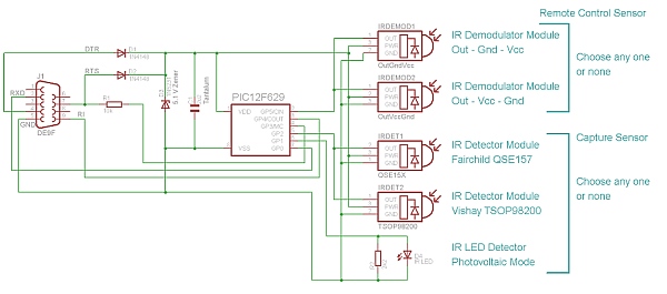
Simple IR capture for multitasking operating systems. The IR Widget captures the infrared signals used by remote controls. It operates in a way that makes it suitable for multitasking environments. The IR Widget is designed to interface with multitasking operating...

The primary components of this doorbell circuit are two NE555 timer integrated circuits (ICs). When switch S1 is pressed momentarily, the loudspeaker emits a bell tone for the duration determined by the monostable multivibrator configuration around IC1. Pressing switch...

This circuit responds to RF signals below the standard broadcast band up to over 500 MHz and provides both visual and audible indications when an RF signal is detected. By adjusting the bias of diode D2 with the R2...

This circuit is a simple analog multiplier. The operation of the circuit can be understood by considering A2 as a controlled gain amplifier. It involves components such as an analog multiplier, a log-antilog circuit, and a summing junction, along...

This is a simple PWM modulator circuit. Comparing the message signal to a ramp or triangular waveform is the simplest way to produce a PWM signal. When the... The PWM (Pulse Width Modulation) modulator circuit operates by comparing a modulating...