
using RF modules with HT12e/d
To implement the described circuit effectively, it is necessary to ensure that the address bits of the encoder are properly connected to a defined logic level to avoid floating states that can lead to unpredictable behavior. Connecting these bits to ground will ensure that they are at a known low state when not actively driven by other signals.
Furthermore, when the transmission circuit keys are open, the input bits D0 to D3 should not be left floating. To mitigate this issue, pull-up resistors should be used. A pull-up resistor connected from each of these data lines to VCC (the positive supply voltage) will ensure that the input bits are held at a high logic level when the keys are open. The specified resistor value of at least 1k ohm is appropriate for most applications, providing a balance between power consumption and response time.
It is also crucial to ensure that the resistors used in both the encoder and decoder circuits are matched in value. Discrepancies in resistor values can lead to mismatched signal levels, which may result in communication errors between the encoder and decoder. Therefore, consulting the datasheet for recommended resistor values and tolerances is essential for maintaining signal integrity.
In summary, the circuit design should include proper grounding of the encoder's address bits, the implementation of pull-up resistors for the data lines, and the selection of matching resistors according to the specifications provided in the datasheet to ensure reliable operation of the encoder-decoder system.Your address bits in the encoder are floating, while those are connected to ground in the decoder. Do the same in the encoder also. Also note that when the keys in the transmission circuit are open, your input bits are floating, So pull up D0 to D3 of the encoder to VCC using a resistor not less than 1k. I hope you`ve selected matching resistors for the encoder and decoder, after going through the datasheet.
🔗 External reference
Related Circuits
Free-space optical (FSO) communication utilizes light as a medium for data transmission. Communication was established between two computers using a laser, independent of any conventional communication methods. Text messages were sent from one PC to another using a system...

This circuit diagram of a digital clock utilizes six common anode seven-segment displays to indicate the time. It does not require microcontrollers or PICs for operation. The circuit operates using the MM5314 integrated circuit, functioning at either 50 Hz...
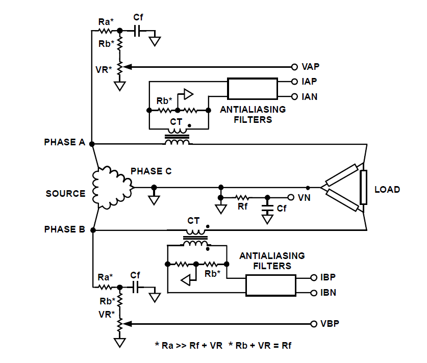
How can a circuit be built for digital readout of three-phase power consumption in a home using a chip like ADE7762? There is an interest in polyphase energy metering. To construct a circuit for digital readout of three-phase power consumption...
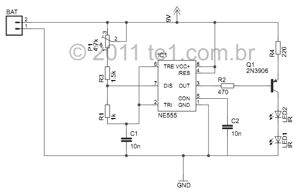
This small device is designed to jam remote controls by directing it at the TV. The circuit utilizes a 555 timer configured as an astable multivibrator, generating a frequency of approximately 38 kHz, which corresponds to the frequency at...
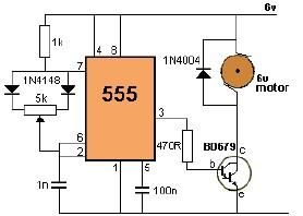
This project utilizes a 555 timer to control the speed of a 6-volt DC motor. Speed adjustment is achieved by rotating a 50 kΩ potentiometer either to the left or right. The circuit employs a 555 timer configured in astable...

This circuit utilizes a 4049 integrated circuit (IC) to control a 2N2222 switching transistor. The transistor, in turn, drives a piezo transducer known as crystal 1. The circuit design begins with the 4049 IC, which is a hex inverter capable...
Warning: include(partials/cookie-banner.php): Failed to open stream: Permission denied in /var/www/html/nextgr/view-circuit.php on line 713
Warning: include(): Failed opening 'partials/cookie-banner.php' for inclusion (include_path='.:/usr/share/php') in /var/www/html/nextgr/view-circuit.php on line 713