
Utility Power Supply
The circuit design ensures reliable operation while maintaining a compact form factor, making it suitable for everyday electronics development tasks. The choice of using standard components not only simplifies assembly but also enhances the availability of replacement parts. The use of dual regulators for lower voltage outputs minimizes thermal stress, thereby increasing the longevity of the components. Moreover, the protective diodes contribute to the robustness of the power supply, safeguarding it against potential damage from incorrect connections. The implementation of fixed voltage outputs streamlines the workflow for developers, allowing for efficient testing and prototyping without the need for constant voltage adjustments. Overall, this power supply represents a practical solution for users requiring reliable, fixed voltage outputs in their electronic projects.Its main feature is a selection of outputs at standard fixed voltages used in electronics. Because the outputs are fixed you do not have to worry if the voltage is correct, you just plug the wire in. It is quick and easy to use. You will probably still need a conventional variable power supply to test circuits over a range of voltages - but this is the one that you will use for day-to-day development.
This power supply was intended to be straight forward and easy to use without controls that needed to be adjusted. It should supply all the standard voltages commonly used in electronic circuits at 500mA or more. The outputs are enabled by the output switch. This instantaneously disconnects the output, compared to the power switch, which, when turned off, can leave the outputs powered for some seconds due to the charge in the filter capacitors. The only downside is that there is no provision for current limiting. in the event of a short or something similar going wrong this power supply will attempt to drive 1. 5 amps through your test circuit. Current limiting was left out because it would be difficult to properly implement and it would result in something that had to be adjusted - which was just what this project was trying to avoid.
Standard range fixed resistors are used to set the output voltages, and because of this careful attention given was to ensure that the values selected gave an result that was as close as possible to the desired voltage. In this design the maximum error due to the values of the resistors chosen is 0. 89% and in most cases it is less than 0. 5%. These resistors are specified as 1% tolerance and the LM317 and LM337 regulators have a tolerance of 1% also.
So, the maximum error would be the sum of these (ie, 3%), but in most cases would be somewhat less. This is much better than the standard tolerance for these voltages which is 5%. In the prototype the 3. 3V output actually produced 3. 299V, an error of 0. 03% (close to the error of the measuring DMM). The 5V output actually produced 4. 994V or an error of 0. 12%. Variable resistors could have been used to trim the output voltage to a precise value but, given the results, that would have been unnecessary and would have introduced a source of unreliability. The circuit is reasonably conventional. The two diodes around each regulator are there to protect the regulator from unusual events such as the output being connected to a negative or higher voltage.
No specialised components are used, the voltage select switch (+/- 9/12/15V) is a center off switch with three positions. All resistors (with the exception of the current limiting resistors for the LEDs) should be 1% metal film.
The +5V and +3. 3V regulators take their input from the output of the regulator which supplies the +9/12/15 volts. The reason for this is to spread the heat dissipation involved in supplying a low voltage like 3. 3V across two regulators rather than one. For example, when the top regulator is set to 12V and the 3. 3V regulator is supplying 1 amp both the regulators will be dissipating approx 9 watts. Whereas, if one regulator was used to supply 3. 3V from the 21V supply the dissipation in that one regulator would be almost 18 watts. The power supply was built into a small bench case with each regulator and its associated components assembled on small pieces of veroboard. The regulators were bolted onto a heatsink and the veroboard that they were attached to were simply supported by the legs of the regulators.
The power supply was so simple that nothing more sophisticated than that was required. Each regulator must be attached to a substantial heatsink. If a single heatsink is used then it should be of reasonable size as it could be called on to dissipate up to 20 watts. Typically a heatsink with less than 2. 5 degrees per watt should be selected. For example, Altronics H0574 or Jaycar HH-8570. Note that insulating gr 🔗 External reference
Related Circuits
Four simple 12V power supply circuits are designed to provide output voltages close to 12V. The first power supply circuit utilizes a BD139 transistor, a zener diode, and several passive components. Each schematic is straightforward to assemble and will...
This simple circuit indicates the amount of power delivered to a loudspeaker. The dual-color LED displays green at an applied power level of approximately 1 watt. At 1.5 watts, it glows orange, and above 3 watts, it shines bright...
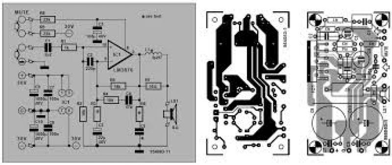
Amplifier with IC number TDA7293 for processing sound systems. This amplifier includes inputs for a radio, TV, stereo, or other line-level devices. It also features a phono input for a record player, guitar, microphone, or other unamplified sources. With...
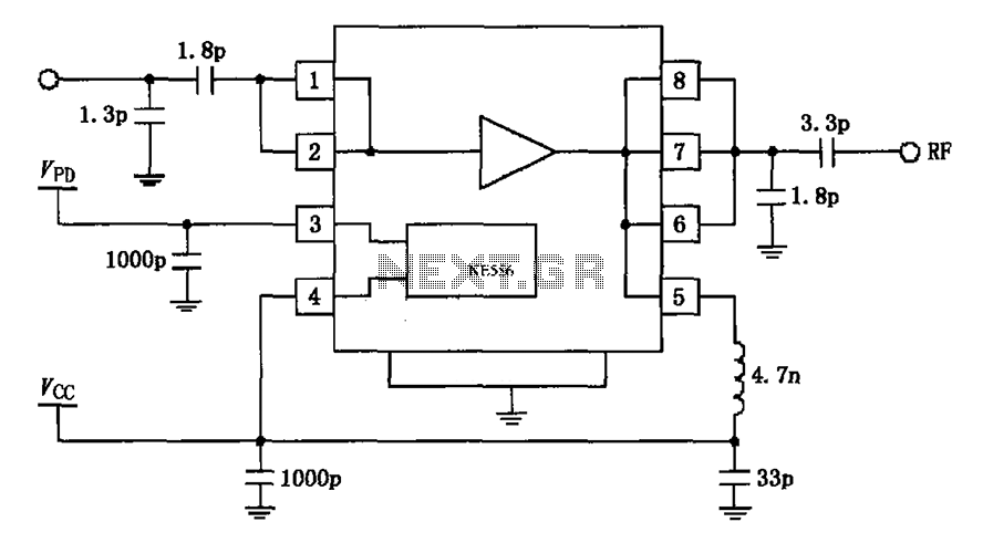
The circuit depicted in the figure is based on the RF2126, a 2450 MHz end-stage linear power amplifier. The radio frequency (RF) signal enters through input pin 1 and is subsequently amplified by the amplifier stages (pins 5, 6,...
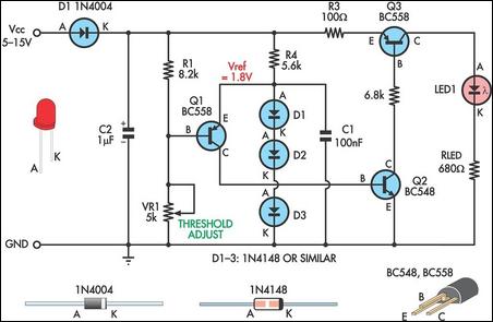
This is a simple low supply rail detection circuit that is inexpensive and can be assembled in approximately 20 minutes. It operates with low power consumption, making it suitable for integration into battery-powered devices. The circuit utilizes three low-cost...
The air-cored inductor L1 is constructed using 13 turns of 1mm diameter enamelled copper wire, featuring an inner diameter of 10mm. The completed inductor is positioned over R7, with its terminals soldered to those of the resistor. All electrolytic...