
Valentines Day POV display using ATtiny13 and Arduino IDE
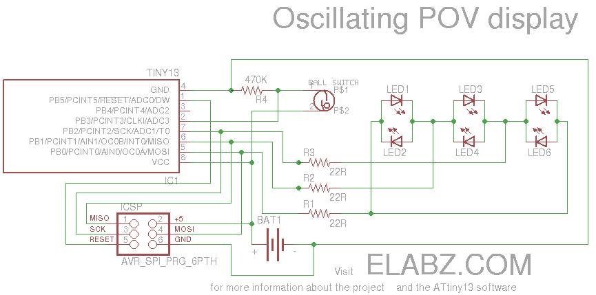
The project involves creating a movement-sensing box of chocolates that incorporates an LED display to convey a message, making it an innovative gift for Valentine's Day. The design utilizes an ATtiny13 microcontroller, which is suitable for low-power applications, and an Arduino platform for ease of programming and prototyping.
The circuit consists of the following key components:
1. **ATtiny13 Microcontroller**: This serves as the main controller for the project. It is responsible for processing input from the motion sensor and controlling the output to the LED display.
2. **Motion Sensor**: A passive infrared (PIR) sensor or an accelerometer can be used to detect movement. When motion is detected, the microcontroller triggers the LED display to light up with a pre-programmed message.
3. **LED Display**: A series of LEDs or a small LED matrix can be employed to display the message. The choice of display will affect the complexity of the circuit and the programming required.
4. **Power Supply**: A battery pack or USB power source can be used to power the circuit. The ATtiny13 is designed for low power consumption, which is ideal for battery-powered applications.
5. **Resistors and Capacitors**: These components are necessary for current limiting and signal smoothing, ensuring that the microcontroller operates reliably.
The circuit can be built on a breadboard for initial testing before being finalized onto a printed circuit board (PCB). The programming is typically done using the Arduino IDE, which allows for easy integration of libraries for handling the LED display and motion sensor.
In summary, the movement-sensing box of chocolates combines simple electronics with creative design to produce a unique Valentine's Day gift. The project encourages exploration of microcontroller programming and circuit design, making it suitable for both beginners and experienced hobbyists.Smart Valentine`s Day gift - a movement-sensing box of chocolates with an LED message! Circuit diagram and How to build the project on ATtiny13 and Arduino. 🔗 External reference
Related Circuits

This circuit utilizes the SIEMENS and UAA180 rectification measurement circuits for accurate signal processing, centered around the TL072 integrated circuit (IC2B). Calibration occurs in 3dB increments, ensuring a high level of precision for measuring incoming acoustic signals. The LEDs...
This circuit demonstrates a straightforward method for incorporating text information into a composite video signal that may be at an undefined DC level. It is essential that the text generator and the composite video source utilize the same synchronization...

This design outlines a power supply circuit capable of producing a 5V source voltage. The circuit is constructed using TTL integrated circuits (ICs) and features a simple design. In circuits utilizing TTL ICs, the supply voltage is critical, as...
The gain control enables the oscillator to maintain a nearly constant output across its range. The circuit operates within a frequency range of 160 kHz to 12 MHz while producing a consistent amplitude. The oscillator circuit described utilizes a gain...
This is a small and simple unit that can be utilized for home security purposes. In this fire alarm circuit, a thermistor functions as the heat sensor. When the temperature increases... The fire alarm circuit described utilizes a thermistor, a...
Utilize this cell phone charger circuit along with a 1.5V battery when there is no main power available and charging your phone is necessary. This cell phone charger circuit is designed to provide a reliable charging solution using a 1.5V...