
Vire 7 Starter GeneratorCircuits
The circuit diagrams for the Bosch and Delco-Remy Starter-Generators serve as essential references for understanding the electrical configurations and operational functionalities of these starter systems. Each diagram is tailored to the specific characteristics of the respective starter-generator, highlighting the differences in circuit design and component integration.
The Bosch Starter-Generator circuit typically incorporates a robust starter relay, which is responsible for engaging the starter motor, and a voltage regulator that stabilizes the output voltage to the battery and electrical system. The design ensures that the starter motor receives adequate power to initiate engine cranking while preventing overvoltage conditions that could damage sensitive electronic components.
Conversely, the Delco-Remy Starter-Generator circuit may feature a slightly different arrangement of relays and voltage regulation mechanisms, reflecting variations in design philosophy and operational requirements. This circuit also emphasizes the importance of reliable connections and component ratings to ensure the efficient functioning of the starter-generator system.
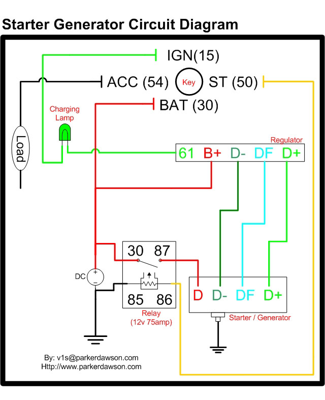
The schematic provided includes detailed annotations regarding the cross-sectional areas of the cables used in the circuit. The thinner lines, representing cables with a cross-section of 2.5 sq. mm, are typically utilized for lower current applications, such as signal wiring or control circuits. In contrast, the thicker lines, indicating a cross-section of 16 sq. mm, are designated for high current paths, such as those connecting the starter motor and battery, ensuring minimal voltage drop and heat generation during operation.
Understanding these diagrams is crucial for technicians and engineers involved in the maintenance and repair of automotive electrical systems, as they provide a clear visual representation of the interconnections and component specifications necessary for troubleshooting and effective system management.Circuit diagrams for both a Bosch and a Delco-Remy Starter-Generator (yes, the circuits are different). Unfortunately, due to a computer crash, I lost both the diagrams and his E-mail address. However, I was able to recover the E-mail and the diagram in May 2004, so here they are, at the bottom of the page.
A big "Thank you" to Sampo, two years behind schedule! A month after recovering the scanned images, I also recovered a diagram sent to me by Vis, the Webmaster at. It`s a schematic of a circuit with separate starter relays and voltage regulators. Thanks Vis. The cross section of the cables indicated by the thinner lines in the diagram is 2. 5 sq. mm (0. 0039 sq. in). The cross section of the cables indicated by the thicker lines is 16 sq. mm (0. 025 sq. in). 🔗 External reference
Related Circuits

The extended delta decompression starter is designed to manage the operation of a three-phase motor during startup. It involves the initial connection of the motor's three-phase winding set to facilitate a reduced voltage startup, which is achieved through a...
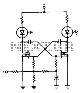
A pair of non-zener MOSPOWER transistors, a pair of LEDs, and a simple RC circuit create an easy sequential flasher with nearly unlimited sequencing time, ranging from momentary flashes to several seconds. The infinite input resistance of the MOSFET...
This manual provides instructions on how to utilize each component in the kit, along with software sketch examples for each. Users can combine components to create automatic systems, such as a lighting controller. The Arduino IDE software has a...
Nissan Sentra 1.6 Liter Manual Transmission Starter Circuit Wiring Diagram. The Nissan Sentra 1.6 Liter manual transmission starter circuit wiring diagram provides a visual representation of the electrical connections involved in the starting system of the vehicle. This diagram is...

This motor starter safeguards single-phase motors from voltage fluctuations and overloads. A key feature is the soft on/off electronic switch, which facilitates user operation. The transformer reduces the AC voltage from 230V to 15V. Diodes D1 and D2 convert...
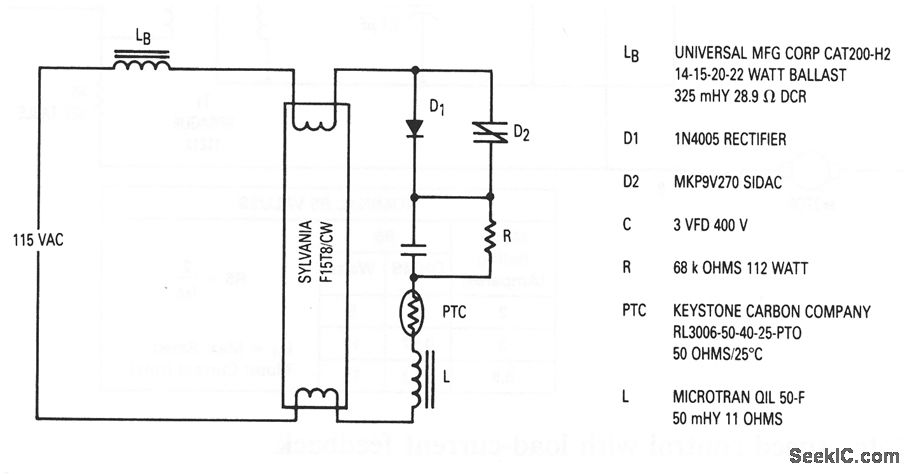
This circuit illustrates a solid-state fluorescent lamp starter that utilizes a SIDAC. In this configuration, the ballast is the same as that employed with a traditional glow-tube starter. The solid-state fluorescent lamp starter circuit operates by leveraging a SIDAC (Silicon...