
controlling feedback on colpitts oscillator(VHF/FM)
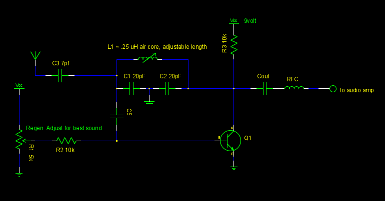
The objective of the oscillator is to tune it to the same frequency as an FM station. This configuration may lead to two outcomes: a) If the gain is insufficient (below the oscillation threshold), the circuit functions as a regenerative AM receiver using slope detection; or b) if the circuit oscillates, incoming RF signals at the same frequency can modulate the amplitude for detection. The output from the oscillator was routed through capacitor C4 and a radio frequency choke (RFC) to an audio amplifier. By adjusting the base bias potentiometer, static was introduced into the audio amplifier. Further tuning of C1 and C2 allowed for the reception of various FM stations.
The initial design involved variable capacitors with a fixed inductor. However, this setup proved complicated as changing either capacitor affected both the feedback and tuning. Therefore, fixed capacitors (20 pF each) were employed alongside a variable inductor, which was adjusted by physical manipulation. This adjustment improved the circuit's functionality, although it initially seemed to eliminate the ability to modify feedback. However, it was discovered that adjusting the base bias altered the transistor's operating point, consequently changing the gain and allowing for feedback control. This configuration provided both regeneration and tuning controls, enabling the reception of numerous stations, including weaker signals adjacent to stronger ones.
The selectivity of the circuit resembled that of a traditional regenerative receiver. However, adjusting the regeneration control also shifted the tuned station due to the changes in the transistor's stray capacitance with varying operating points. The tuning of the inductor was necessary to achieve desirable reception, but if the gain was too high or low, a readjustment of the regeneration control would often lead to a shift to a different station, necessitating further tuning adjustments. With careful manipulation, the circuit could maintain a stable reception of a selected station, even outperforming a commercially available boombox in terms of station acquisition.
The user expressed interest in improving feedback or gain control without affecting the LC circuit's tuning. While acknowledging the existence of various super-regenerative designs, the simplicity of the current regenerative design was preferred. A potential enhancement considered was the use of a dual-gate FET with a variable voltage applied to the second gate, or a cascaded pair of FETs or transistors, with the upper device functioning as a controller similar to an automatic gain control (AGC) circuit. Reference to a circuit from Sprat Issue No. 70, Spring 1992, featuring a TRF receiver designed by Nicky, was suggested for further exploration.
In summary, this common emitter Colpitts oscillator circuit serves as a versatile platform for FM reception, demonstrating effective feedback control and selectivity, while also providing a foundation for potential enhancements in gain management and operational stability.A common emitter colpitts oscillator: I used variable capacitors for C1 and C2, and few turns of wire over a pencil for L. R1 and R2 were replaced with a trimmer so I could bias the base however I wanted. Transistor was a nte107. I connected a short length of wire to the LC tank with a small 7pf capacitor. I put my frequency counter leads near the wire, and I get 80 mhz or so. Adjusting the capacitors adjusted the frequency somewhat. Ok, so I have an oscillator. Where does that get me: The idea is if the oscillator is set to the same frequency as an FM station, one of the following may happen: a) If the gain is low (below the point of oscillation) this will just be a regen AM receiver using slope detection or b) if this circuit oscillates, then the incoming RF from the antenna at the same frequency should nudge the amplitude up and down enough to detect. Idea from here: Either I will end up with a non-oscillating regen, or the oscillator will be a detector; I didn`t care, either way would work for me : ) So, next step, I put the output of the oscillator at C4 through a RFC to an audio amp.
I adjusted the base bias pot until some static came through the audio amp. I adjusted C1/C2 and some FM stations come in and out. By adjusting C1/C2/ base pot, you can get a couple stations clearly. My first attempt used variable capacitors and a fixed L. Changing either C1 or C2 changed the station, but since the C1/C2 ratio changed, so did the feedback. It was too complicated to use: changing either capacitor changed feedback AND tune at the same time. So I switched to using fixed capacitors (20pf each) and a variable inductor. (I am physicall stretching/compressing L) This worked, but there was no way to change feedback. Or so I thought: by adjusting the base bias, the operating point of the transistor changed, so the gain changes, the circuit can be adjusted into or out of oscillation.
Now I have a `regen` control, and a `tune` control. With careful adjustment, I can pick out many stations, even weaker stations adjacent to strong stations. It really has the selectivity of a regular old regen receiver. Changing the regen control also changes the station! I think this is because the transistor`s stray capacitance changes as the operating point changes. Not by a lot, but enough. You adjust the L tune, to something you like, but the gain is too high or low. So you adjust the regen, but the circuit jumps to the next station, and you have to readjust L. If you`re careful, you can get it to stick to a station and clean it up until it sounds good. On about 12 inches of wire for an antenna, I was picking out stations that my Sony boombox has trouble getting.
This circuit seems pretty selective, neighboring strong stations don`t seem to influence each other. Usage is similar to the AM regen I started a thread about this time last year, except you do need to be a little more patient with it to get a good signal. Is there a better way to control feedback or gain in a way that won`t affect the tune of the LC circuit I know there`s a lot of super-regenerative designs out there, but this plain regen design is so simple, I`d like to mostly keep it.
one thought would be to use a dual gate FET using a variable voltage on gate two or maybe a cascaded pair using of FETs or transistors, the top one being the `controller` as if in agc circuit. Have a look at this circuit taken from Sprat Issue No 70 Spring 92, it`s a circuit of Nicky`s TRF receiver, might offer
🔗 External reference
Related Circuits
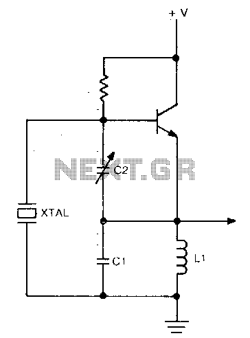
This circuit operates at a frequency range of 30-200 parts per million (ppm) above the series resonance. It is physically simple, yet analytically complex. Additionally, it is cost-effective and exhibits reasonable frequency stability. The described circuit functions within a specific...
The design of this project relies heavily on sensors, which are present in both the control module and the robot. The computer analyzes the signals from these sensors to determine appropriate output actions. The control unit utilizes potentiometers as...
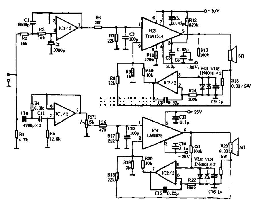
The mechanical and electrical schematic in Figure 5 illustrates a simple circuit comprising several components. The first component is an electronic crossover section utilizing the NE5532 operational amplifier, which is known as the "Emperor of the op-amp." This section...
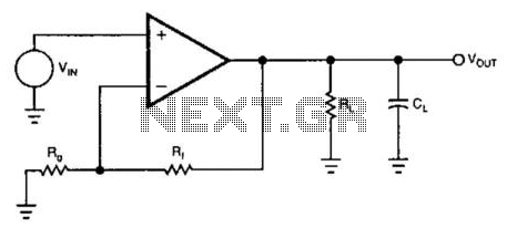
The standard approach for utilizing a current-feedback amplifier to drive a capacitive load involves isolating the load with a resistor in series with the amplifier's output. An improved method utilizes only the amplifier's feedback resistors. The feedback resistors play...
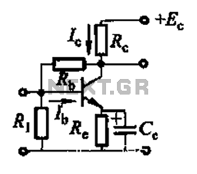
Basic reference transistor bias circuit - Mixed Negative feedback The basic reference transistor bias circuit utilizing mixed negative feedback is a fundamental electronic configuration designed to stabilize the operating point of a transistor. This circuit typically employs a combination of...
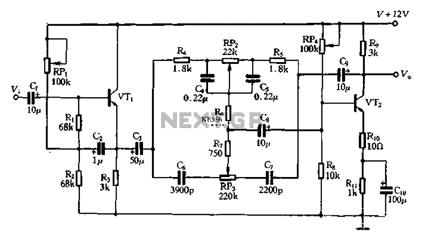
The attenuation circuit is a feedback tone control system that consists of transistors and an RC network. The circuit includes a low tone control potentiometer (RP2) and a treble control potentiometer (RP3). The bass control is influenced by resistor...
Warning: include(partials/cookie-banner.php): Failed to open stream: Permission denied in /var/www/html/nextgr/view-circuit.php on line 713
Warning: include(): Failed opening 'partials/cookie-banner.php' for inclusion (include_path='.:/usr/share/php') in /var/www/html/nextgr/view-circuit.php on line 713