
Variable Power Supply 0-24V

This variable power supply circuit is designed to provide a stable output voltage that can be adjusted smoothly from 0V to 24V, making it suitable for various electronic applications. The core component of the circuit typically includes a linear voltage regulator, such as the LM317, which allows for adjustable output voltage based on external resistors.
The circuit may consist of the following key components:
1. **Transformer**: A step-down transformer is used to convert the AC mains voltage to a lower AC voltage suitable for rectification. The transformer rating must be selected based on the maximum load current and the desired output voltage.
2. **Rectifier**: A bridge rectifier configuration using four diodes is commonly employed to convert the AC voltage from the transformer into pulsating DC voltage. This rectified voltage is then filtered to smooth out the fluctuations.
3. **Filter Capacitor**: A large electrolytic capacitor is placed after the rectifier to reduce the ripple voltage and provide a more stable DC voltage. The value of the capacitor is chosen based on the load current and acceptable ripple voltage.
4. **Voltage Regulator**: The LM317 voltage regulator is used for its adjustable output feature. By connecting two resistors (R1 and R2) to the adjustment pin, the output voltage can be set to the desired level. The output voltage can be calculated using the formula: Vout = 1.25V * (1 + R2/R1).
5. **Control Features**: The circuit may include a potentiometer for adjusting the output voltage. Additionally, it may have a series of indicator LEDs to show the power status and output voltage level.
6. **Short Circuit Protection**: To protect the circuit from damage due to short circuits, a fuse or a resettable fuse (PTC) can be included in the design. This component will disconnect the load in case of excessive current flow, ensuring the safety of the power supply and connected devices.
7. **Output Terminals**: The circuit will have output terminals to connect the load, often with a binding post or banana plug configuration for easy access.
This variable power supply circuit is ideal for laboratory use, DIY projects, or any application requiring adjustable DC voltage. Proper heat sinking for the voltage regulator and careful component selection will enhance the reliability and performance of the power supply.The circuit described here is of an economical smooth variable power supply which offers 0V to 24V. It provides all controls and short circuit.. 🔗 External reference
Related Circuits
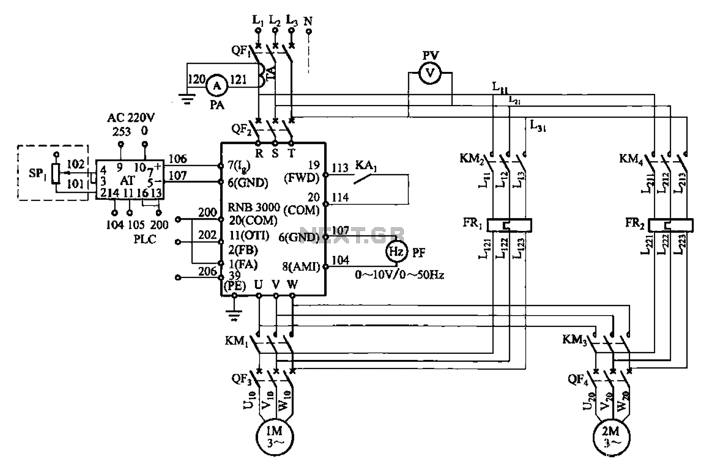
A control circuit for two motors, specifically for frequency control in a constant pressure water supply system, is illustrated in Figure 5-23. The circuit includes fault output terminals labeled 1 and 2, analog feedback current input terminals labeled 6...
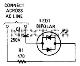
Many electronic circuits require an indication that they are powered. For most AC circuits, a neon lamp is the preferred device. A bidirectional tricolor LED can also be utilized if a capacitor is connected in series with the LED...
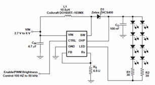
The schematic diagrams for the TPS61042 current LED driver illustrate its capability to power eight LEDs with an efficiency of 81% at 3.6V and 18.6mA. The TPS61042 is commonly utilized in applications such as white LED supply for backlight...
This circuit is designed to drive a low-power speaker using a sound effects module or a noise generator. It can also be utilized to create amplified speakers for computer use. The circuit amplifies the input signal by a factor...
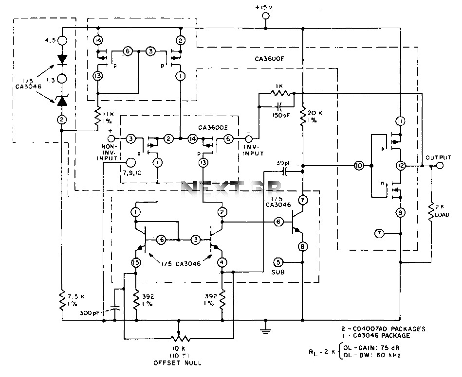
This unity-gain follower amplifier features a CMOS p-channel input, an NPN second-gain stage, and a CMOS inverter output. The integrated circuit components consist of two CA3600E CMOS transistor pairs and a CA3046 NPN transistor array. A zener-regulated leg provides...
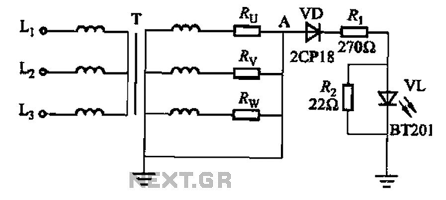
It is well understood that if the power transformer neutral line is disrupted, an unbalanced three-phase load can easily result in overvoltage conditions, potentially damaging electrical equipment such as household appliances and lamps. The neutral circuit alarm system is...