
Variable Voltage Regulator
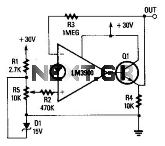
The described circuit utilizes an operational amplifier in a non-inverting configuration, which is a popular choice for applications requiring signal amplification without phase inversion. The gain of the amplifier is set by the feedback resistors R3 and R2, following the formula \( \text{Gain} = 1 + \frac{R3}{R2} \). This allows for precise control over the amplification factor, making it versatile for different applications.
The input voltage is adjustable between 0 and 15 V through resistor R5, which serves as a variable resistor (potentiometer) in the circuit. This feature enables the user to tailor the input signal level according to the requirements of the specific application. The output voltage range of approximately 0.5 to 30 V suggests that the op amp is capable of amplifying the input signal significantly, depending on the gain setting.
To enhance the output current capability, which is often limited in standard op amp configurations, a transistor (Q1) has been added to the output stage. This transistor acts as a current booster, allowing the circuit to drive larger loads without compromising performance. The transistor is likely configured in a common-emitter or emitter-follower arrangement, depending on the desired output characteristics and load requirements.
Overall, this circuit configuration is suitable for various applications, including sensor signal conditioning, audio amplification, and other scenarios where a stable and adjustable DC voltage output is necessary. The careful selection of components and configuration ensures reliable performance across the specified input voltage range. The op amp is wired as a 2 noninverting dc amplifier with a gain that is determined by the R3/R2 ratio. The inp ut voltage to the op amp is variable between 0 and 15 V via R5. The output voltage is therefore variable over the approximate range from 0.5 to 30 V. The available output current has been boosted by adding transistor Ql to the output. 🔗 External reference
Related Circuits
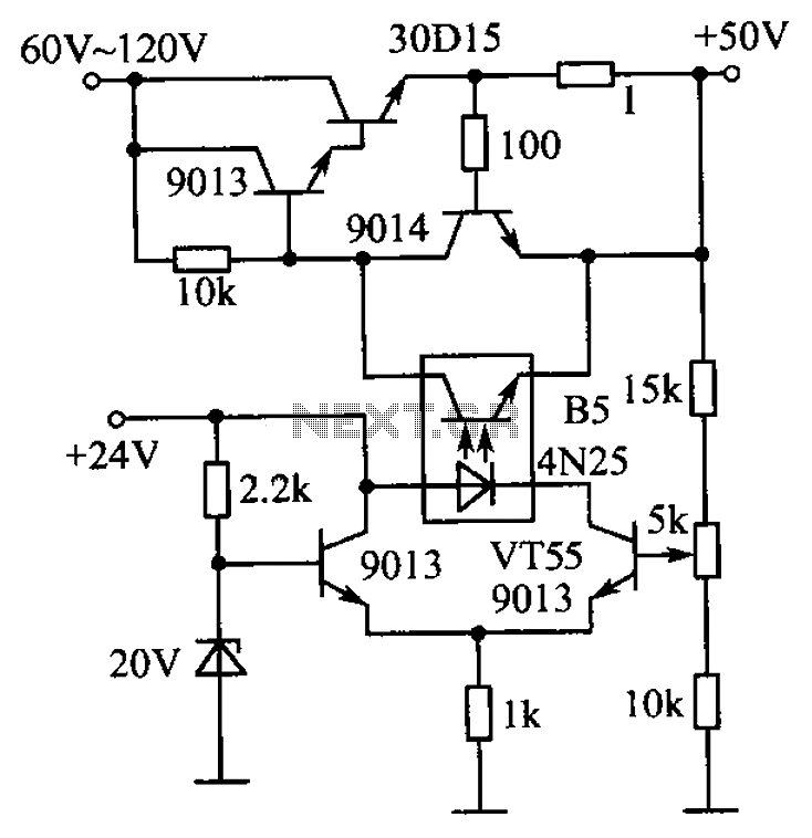
The circuit is illustrated. A standard driving transistor requires a higher breakdown voltage transistor (such as the FIG driving tube 9013). As the output voltage rises, the bias on VT55 increases, leading to an increase in the forward current...
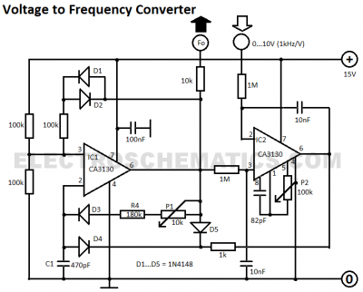
This voltage-to-frequency converter circuit features a voltage-controlled oscillator with a small deviation of 0.5%. The integrated circuit IC1 operates as a multivibrator. The voltage-to-frequency converter circuit is designed to convert an input voltage into a corresponding frequency output. The core...
An alternative approach to utilizing operational amplifiers (op-amps) for power supply regulation is presented. This method necessitates an additional winding on the power transformer to provide the op-amps with a bipolar voltage of +/- 8 volts. The negative voltage...
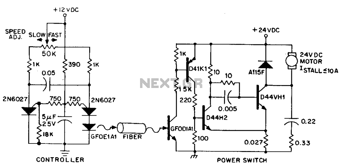
DC power can also be controlled using fiber optics. The circuit provides an insulated speed control path for a small DC actuator motor (less than Vn hp). The control logic is a self-contained module that requires approximately 300 mW...
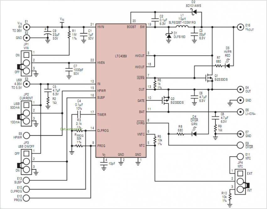
MSP430 microcontroller and I2C-compatible slave peripheral device. Temperature measurement tasks can be accomplished in a variety of ways. The MSP430 microcontroller is a low-power, 16-bit device widely used in embedded systems, particularly for applications requiring efficient power management and precise...
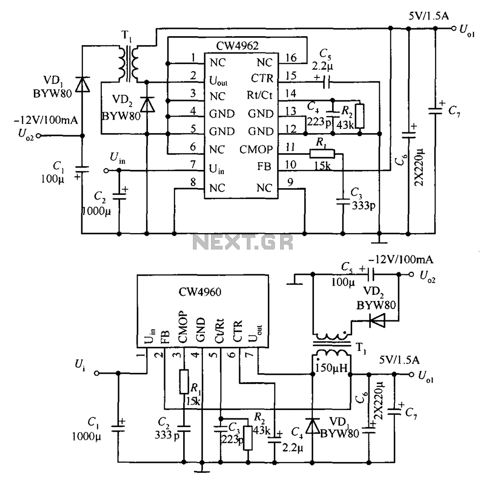
The circuit described is a stabilized power supply utilizing the CW4962 and CW4960 components, providing +5V at 1.5A and -12V at 100mA. The +5V output serves as the main power supply. The output circuit employs a transformer rather than...