
Integrated High Voltage Switching Charger circuit
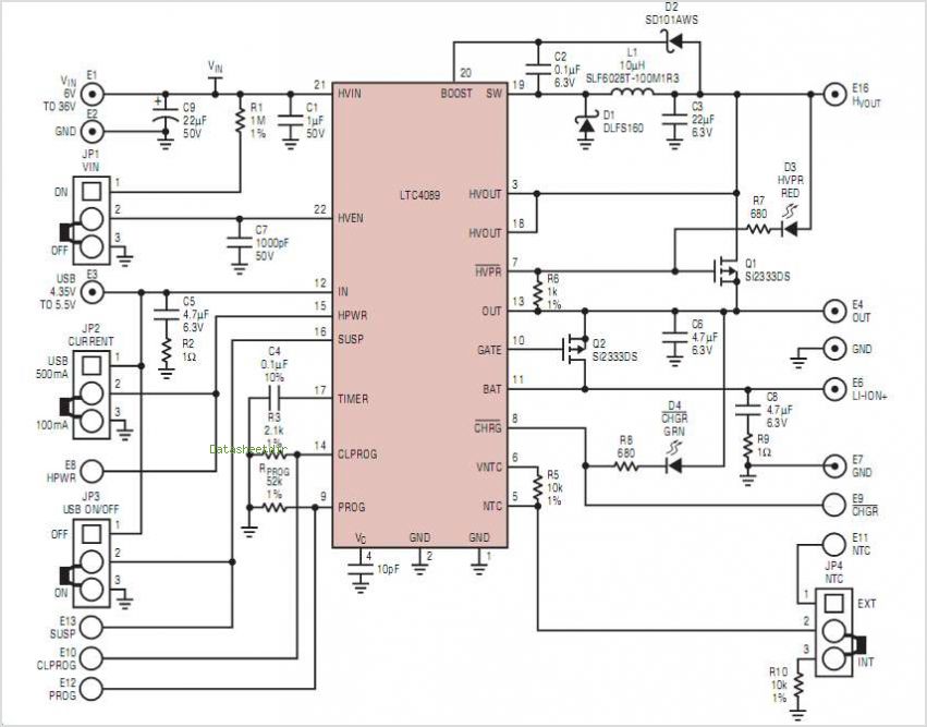
The MSP430 microcontroller is a low-power, 16-bit device widely used in embedded systems, particularly for applications requiring efficient power management and precise control. This microcontroller is equipped with various integrated peripherals, including timers, ADCs (Analog-to-Digital Converters), and communication interfaces such as I2C, which allows for seamless communication with other devices in a network.
The I2C-compatible slave peripheral device serves as a secondary unit in the I2C communication protocol, enabling the MSP430 to communicate with multiple devices using only two wires: the serial data line (SDA) and the serial clock line (SCL). This configuration simplifies the wiring and reduces the number of pins required on the microcontroller.
Temperature measurement tasks can be implemented using several methods, including the integration of temperature sensors such as thermistors, RTDs (Resistance Temperature Detectors), or digital temperature sensors like the DS18B20. The choice of sensor depends on the required accuracy, response time, and environmental conditions.
In a typical application, the MSP430 microcontroller would read temperature data from the I2C-compatible sensor, process the information, and potentially control other components based on the measured temperature. The microcontroller's ADC can be utilized to convert the analog signal from a thermistor or RTD into a digital value for further analysis.
Overall, the combination of the MSP430 microcontroller with an I2C-compatible slave device creates a flexible and efficient system for temperature measurement and control, suitable for various applications such as environmental monitoring, HVAC systems, and industrial automation.MSP430 micro-controller and I2C-compatible slave peripheral device. As stated earlier, temperature measurement tasks CAN be accomplished in a number of different 🔗 External reference
Related Circuits
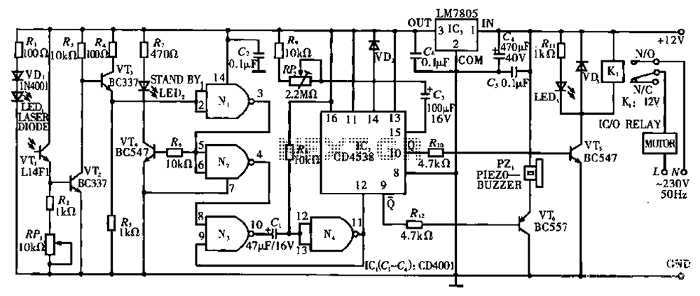
Circuit T operates on the principle of utilizing a laser diode LED as a light emitter. This circuit incorporates a laser diode that serves similar functions as a light-emitting diode. It features a resistor (R) and a diode (VD)...
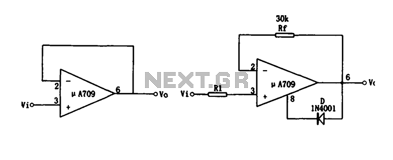
Figure (a) illustrates a voltage follower circuit, which serves as a specific instance of an in-phase amplifying circuit. The input signal originates from an integrated operational amplifier. At the conclusion of the introduction phase, the feedback resistor is set...
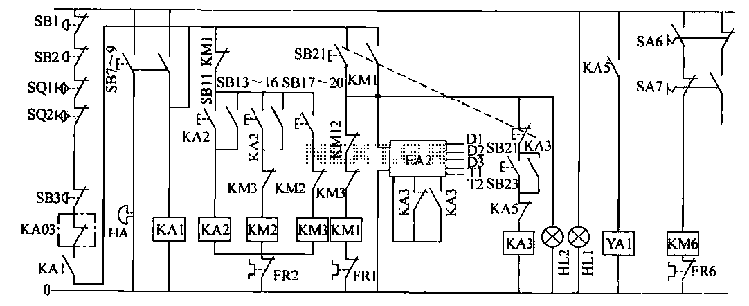
The operation control circuit is primarily managed by the button switch SB21. The contactor KM1, composed of the main contactor KM1, directly controls the operation of the main motor M1. The main motor M1 serves as the prime mover,...
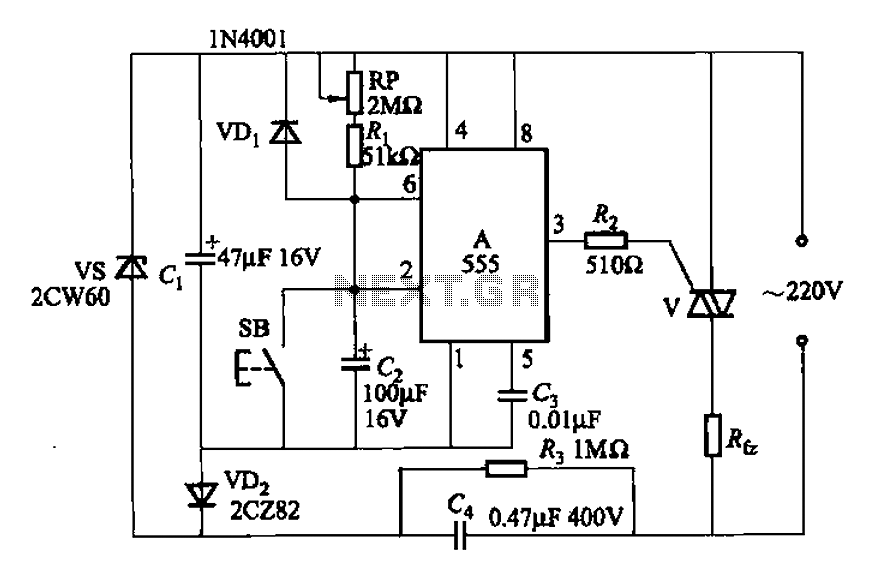
A 555 four-base integrated circuit delay circuit is designed to facilitate a transition from high to low output. When the button SB is pressed, the output is set to high, and after a specified delay, the output transitions to...
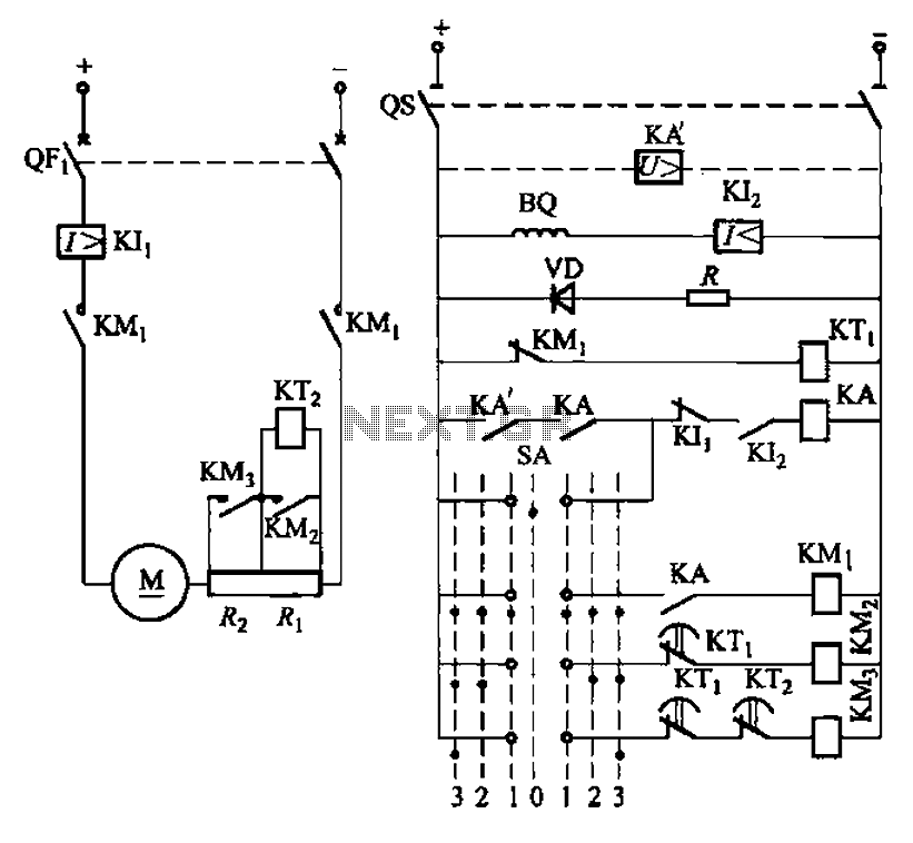
The circuit depicted in Figure 3-190 includes an armature circuit with two startup resistors, Ri and Rz, connected in series through the main switch SA to facilitate starting, stopping, and speed control. During the startup phase, two relays, KTi...
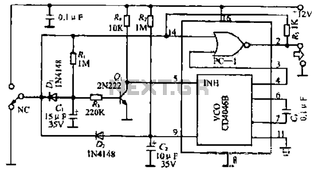
The figure illustrates a circuit involving dark tomb electric locks, specifically the fti: al: 4046B and XOR gate as the primary control mechanism. It emits pulses and utilizes silicon for successive pulse generation. The circuit operates with a normal...
Warning: include(partials/cookie-banner.php): Failed to open stream: Permission denied in /var/www/html/nextgr/view-circuit.php on line 713
Warning: include(): Failed opening 'partials/cookie-banner.php' for inclusion (include_path='.:/usr/share/php') in /var/www/html/nextgr/view-circuit.php on line 713