
Variety of signal generator circuit
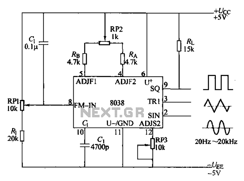
The ICL8038 integrated circuit is a versatile waveform generator designed for audio applications, capable of generating precise waveforms at various frequencies. The circuit's operation is primarily controlled by the external components connected to it, specifically the resistors RA, RB, and the capacitor C1, which dictate the frequency and shape of the output waveform.
To achieve a desired output frequency, the values of RA and RB can be adjusted. The relationship between these resistors and the capacitor C1 is critical, as they form an RC timing network that sets the oscillation frequency. The output frequency fo can be calculated using the formula that incorporates these components, allowing for a wide range of frequencies to be generated, from low audio frequencies up to the upper limits of human hearing.
The potentiometer RP1 serves a dual purpose: it allows for fine-tuning of the output frequency while also enabling the user to set the DC potential Ua at pin 8. This potential influences the frequency output, with the characteristic that increasing Ua generally lowers the frequency output. This feature makes the ICL8038 particularly useful in applications requiring frequency modulation, as the output can be adjusted smoothly across the specified range of 20Hz to 20kHz.
When configuring the circuit for dual power supply operation, it is essential to ensure that the DC level of the output waveform is maintained at zero volts. This configuration is ideal for applications where the waveform needs to oscillate symmetrically around ground potential. In contrast, when employing a single power supply, care must be taken to set the DC level of the output waveform to Uw/2, which shifts the waveform accordingly and may be necessary depending on the requirements of the connected load or subsequent stages in the signal processing chain.
Overall, the ICL8038 is a highly adaptable and efficient component for generating various waveform outputs, making it an invaluable tool in electronic design for audio and signal processing applications. Audio function generator integrated circuit ICL8038 composition can produce a square wave, triangle wave and sine wave, as shown in Figure 11-8. Electrical resistance and poten tiometer RP1 Shu used to determine the 8-pin DC potential Ua, usually taken team 2Ucr/3, Zhang higher, IA JB and smaller, the output frequency is lower, and vice versa. Therefore, ICL8038 also known as voltage-controlled oscillator (vc0) or frequency modulator (FM). RP1 adjustable frequency range is around 20Hz-20kHz. Us can also provide a fixed potential by seven feet, this time, the output frequency fo decided only by the RA-RB and the capacitor c1.
Ucc, when dual power supply, the DC level of the output waveform is zero. When using a single power supply, the DC level of the output waveform is Uw/2
Related Circuits
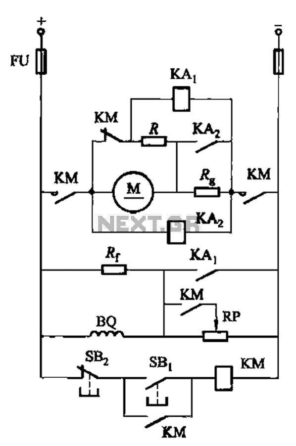
The circuit illustrated in Figure 3-197 features a dish adjust rheostat (RP) that allows for the adjustment of field current, which in turn modifies the motor speed. The circuit operates by utilizing a rheostat, which is a variable resistor that...
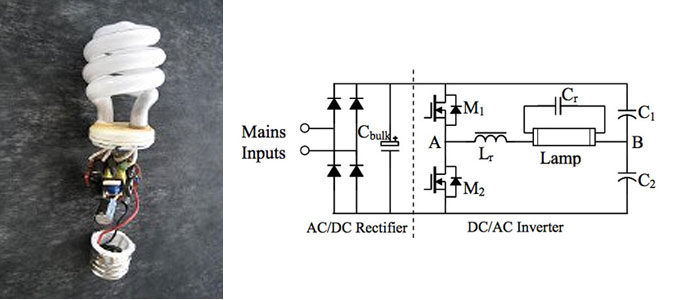
A circuit diagram for a 40W, 230V transistor-based electronic ballast is required. What steps are involved in designing an electronic ballast? An electronic ballast is a device used to regulate the current to fluorescent lamps and provide sufficient voltage to...
A gas leak detector circuit that detects the leakage of LPG gas and alerts the user through audio-visual indications. The circuit operates off a 9V PP3 battery. A Zener diode is used to convert 9V into 5V DC to...
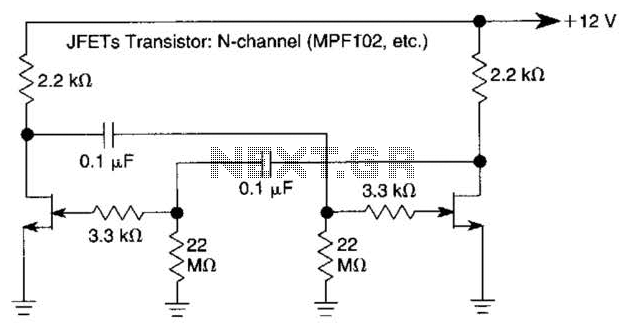
The use of JFETs allows for high resistance and long time constants in this very low frequency multivibrator. The values indicated are for operation at 0.15 Hz. In the context of electronic circuit design, a multivibrator is a circuit that...
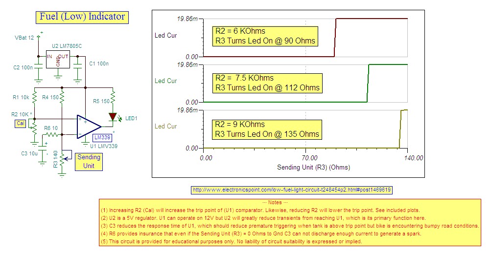
Research indicates that the sender will register a resistance of 100 ohms when the fuel tank is empty, making a trigger reading of 80 ohms optimal. The fuel gauge sender is a critical component in monitoring the fuel level within...
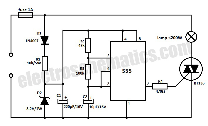
This 220V mains operated solid-state flashing lamp circuit utilizes a 555 timer integrated circuit (IC) to manage the ON and OFF durations of a triac that regulates power to the load. The circuit operates at a mains voltage of 220V,...