
Vco Circuit Circuit
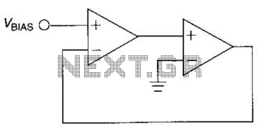
The described voltage-controlled oscillator (VCO) circuit employs the TL082 operational amplifier, which is known for its low noise and high-speed performance. The circuit configuration typically includes feedback components that create a positive feedback loop, essential for sustaining oscillations. The output frequency is influenced by the values of resistors and capacitors used in the feedback network, which dictate the timing characteristics of the circuit.
In this configuration, the TL082 op-amp operates in an inverting or non-inverting mode, depending on the design specifics. The frequency of the oscillation can be modulated by adjusting the bias supply voltage, which alters the gain and frequency response of the op-amp. This provides a versatile means of generating sinusoidal waveforms at various frequencies, making the circuit suitable for applications such as signal generation, modulation, and testing.
The circuit may also include additional components such as diodes for waveform shaping or filtering capacitors to refine the output signal. The simplicity and low cost of the design make it an attractive choice for both educational purposes and practical applications in electronic projects. Careful selection of components and layout considerations are essential to ensure stable oscillation and minimize distortion in the output waveform. The output frequency of this simple low-cost active voltage-controlled oscillator circuit is based upon the inherent frequency dependent characteristics of our operational amplifier. The oscillator circuit shown uses a TL082 op amp. When power is applied, the circuit generates a sinusoidal wave. The frequency of oscillation can be changed by varying the bias supply. 🔗 External reference
Related Circuits
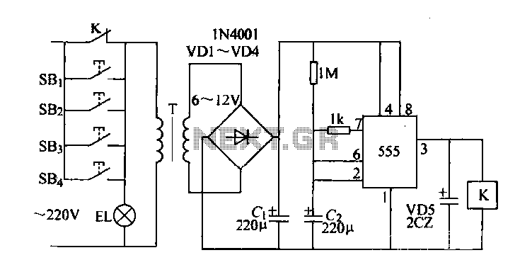
Control buttons SB1 to SB4 can be installed in various positions within a corridor. By pressing any one of these buttons, the EL horse lights will turn on. After releasing the button, the transformer and rectifier supply power to...
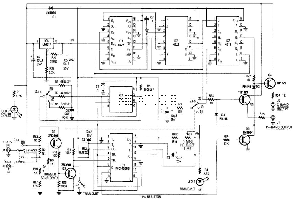
This circuit is a system designed to generate a pulsed modulation signal for a Gunn diode microwave oscillator. It features several preset speed settings (S3 a and b). A 555 timer is employed in conjunction with a frequency divider...
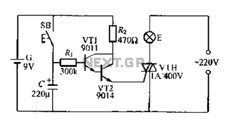
A delay circuit utilizing an electric lamp. Normally, the thyristor VTH remains off, and the lamp E does not illuminate. The lamp turns on when needed, controlled by the FSH, with the VT1 and VT2 components forming a composite...
The time is set by potentiometer R2, which provides a range from 1 second to 100 seconds, using a timing capacitor C1 of 100 µF. The output at pin 3 is normally low, keeping the relay in the off...
To complement the 60 Watt MOSFET audio amplifier, a high-quality preamplifier design was necessary. A discrete component topology, utilizing +24V and -24V supply rails, was selected, minimizing the transistor count while ensuring low noise, very low distortion, and a...
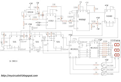
This circuit consists of a temperature sensor, amplifier, voltage-to-frequency (V/F) converter, a three-digit binary coded decimal (BCD) counter, a time base, and seven-segment LED displays. In addition to the 9400 V/F converter, other integrated circuits (ICs) required for this...