
Power-frequency meter

The circuit employs a zener diode as a key component in the waveform conversion process. The zener diode is connected in such a way that it operates in reverse breakdown mode, allowing it to clip the peaks of the incoming sine wave. This clipping action transforms the smooth sine wave into a square wave, suitable for frequency measurement.
The calibration process involves adjusting a 5 k ohm potentiometer, which is integrated into the circuit. This potentiometer allows for fine-tuning of the circuit's response to ensure accurate frequency readings. The output from the zener diode is fed into a frequency meter, which is designed to interpret the square wave signal.
The 100 µ meter is calibrated to display frequency directly in hertz, providing a user-friendly interface for measurement. The design of the circuit ensures that it is capable of handling a range of frequencies while maintaining accuracy and reliability. Proper attention to component selection, such as the zener diode's breakdown voltage and the characteristics of the potentiometer, plays a crucial role in the overall performance of the meter.
This type of circuit is commonly used in various applications where frequency measurement is essential, such as in telecommunications, audio equipment testing, and signal processing. The simplicity of the design, combined with the effectiveness of the zener diode for waveform conversion, makes it a practical solution for frequency measurement tasks.The meter uses a zener diode to form square waves from input sine waves. After calibration with the 5 k ohm potentiometer, the 100 µ meter reads directly in hertz.
Related Circuits
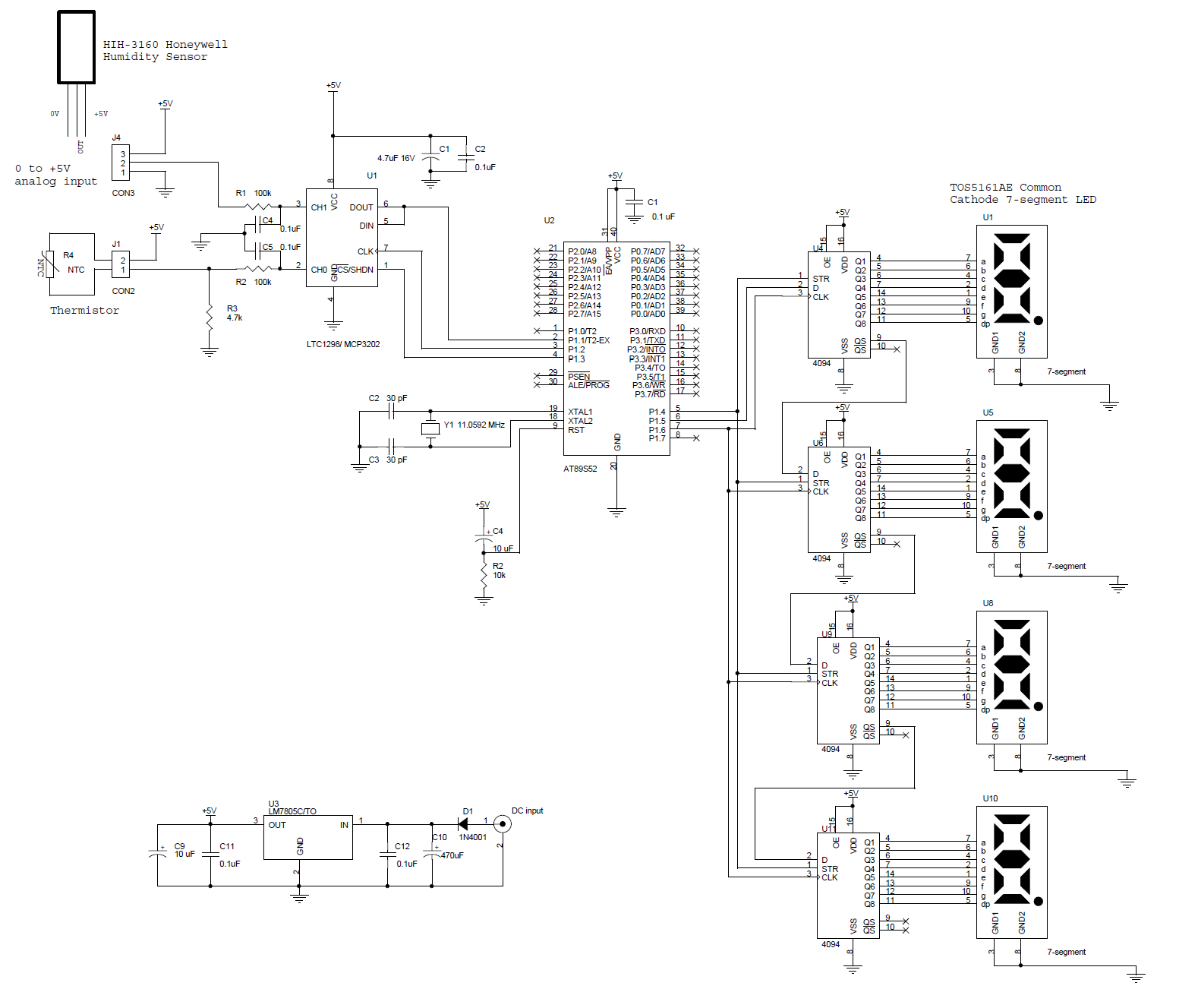
This circuit features a microcontroller AT89S52 thermometer paired with an LTC1298 12-bit ADC. The program is written in C language and incorporates digital filtering along with an interface for an LED display. The temperature readings have a sensitivity of...
IC4 serves as a counter and oscillator combination, which is the pivotal component of the circuit. The oscillator generates an AC signal that is output on pin 7. This signal is routed through a voltage divider composed of resistors...
This Field Strength Meter has been specially designed for our FM bugs. It is capable of detecting very low power transmitters and will assist enormously in peaking many of our FM transmitters that have a coil in the output...
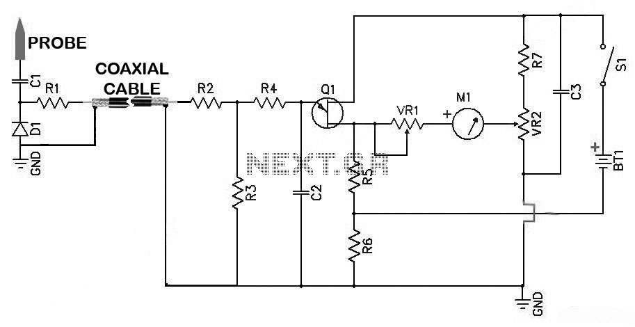
Sensitive RF Voltmeter Probe Circuit. This circuit measures RF voltages beyond 200 MHz and up to about 5 V. PARTS LIST: R1 - 4.7 MΩ, R2 - 1 MΩ, R3 - 1 MΩ, R4 - 100 kΩ, R5 -...

The Allegro A8732 is a Xenon photoflash charger integrated circuit (IC) specifically designed for ultra-low power, compact cameras, especially in mobile devices such as camera phones. It utilizes primary-side voltage sensing, which eliminates the need for a secondary-side resistive...
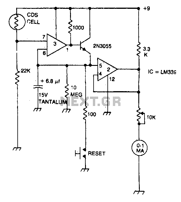
A strobe light meter captures the peak flash intensity and retains it long enough to provide a reading. The reset button must be pressed prior to each measurement. The strobe light meter operates by detecting the peak intensity of light...