
very useful timed beeper
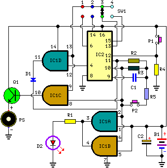
The circuit utilizes an integrated circuit (IC) configuration that facilitates timing and sound generation through a combination of oscillation and control elements. The reset function is initiated by pressing switch P1, which triggers a reset on IC2, causing it to start oscillating at a frequency set by the resistor R3 and capacitor C1. The calculated oscillation frequency is approximately 4Hz, allowing for a slow flashing of LED D2, which serves as a visual indicator of the circuit's operational status.
SW1 plays a crucial role in determining the timing duration by selecting the appropriate pin on IC2. This flexibility enables users to tailor the timing based on their specific requirements. When the designated pin of IC2 transitions to a high state, it activates IC1C, which in turn drives transistor Q1. This action results in the piezo sounder emitting beeps that synchronize with the flashing LED, enhancing the circuit's auditory feedback.
The timing mechanism is designed to count for about 7.5 seconds, after which pin 4 of IC2 transitions high, signaling IC1D to disable the oscillator through diode D1. The circuit includes a provision for early termination of the counting process via switch P2, which, when pressed, compels IC2 to oscillate at a much higher frequency. However, it is important to note that the circuit does not reset instantaneously. Depending on the timer settings, there may be a delay before the counting ceases, especially if the button is pressed soon after the circuit initiation.
For applications requiring a fixed timing duration, it is recommended to bypass the switch and connect pins 9 and 13 of IC1 directly to the appropriate pin on IC2. Adjustments to R5 can influence the reset timing; reducing its value may hasten the reset process, but caution must be exercised, as excessively low values could disrupt the oscillation process. This circuit design effectively combines visual and auditory signals to provide feedback on timing operations, making it suitable for various timing and alert applications.Pushing on P1 resets IC2 that start oscillating at a frequency fixed by R3 & C1. With values shown, this frequency is around 4Hz. LED D2, driven by IC1A & B, flashing at the same oscillator frequency, will signal proper circuit operation. SW1 selects the appropriate pin of IC2 to adjust timing duration: When the selected pin of IC2 goes high, IC1C
drives Q1 and the piezo sounder beeps intermittently at the same frequency of the LED. After around 7. 5 seconds pin 4 of IC2 goes high and IC1D stops the oscillator through D1. If you want to stop counting in advance, push on P2. SW1 can be any type of switch with the desired number of ways. If you want a single fixed timing duration, omit the switch and connect pins 9 & 13 of IC1 to the suitable pin of IC2. The circuit`s reset is not immediate. Pushing P2 forces IC2 to oscillate very fast, but it takes some seconds to terminate the counting, especially if a high timer delay was chosen and the pushbutton is operated when the circuit was just starting.
In order to speed the reset, try lowering the value of R5, but pay attention: too low a value can stop oscillation. 🔗 External reference
Related Circuits
Although many album titles that were once available on vinyl are gradually being released on CDs, not all titles are accessible. It is possible that there are valuable records in a collection that one might wish to convert to...
Ty - Concerning the updated schematic of the AF/PI stage, it appears that resistor R45 is not present. Additionally, the disk capacitor bypassing R44 is marked as 68nF750 with a tolerance of 10%, which is presumed to be the...
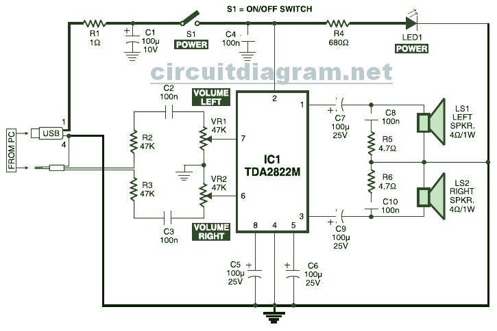
USB Powered Stereo PC Multimedia Speaker Circuit Diagram. This circuit is powered by a 5V DC source obtainable from the USB port of a computer. When the electrical power switch S1 is turned to the "on" position, the 5V...
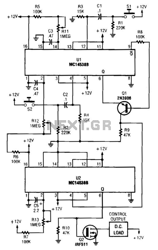
When switch SI is closed, pin 9 of operational amplifier U1 goes low, activating transistor Q1 for a predetermined duration. If switch S2 is closed during this time, transistor Q2 is activated for another predetermined duration. Resistors R1 and...
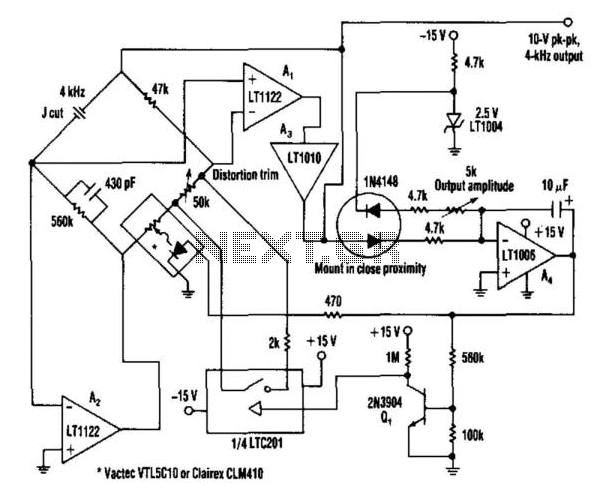
This oscillator utilizes a bridge circuit with an optoisolator functioning as a gain-control device. The resultant distortion can be maintained at 9 ppm (0.0009%) with appropriate adjustments. The oscillator circuit described operates using a bridge configuration, which is a common...
The UTC CXA1191 is a one-chip AM/FM radio integrated circuit (IC) designed for use in radio-cassette tape recorders and headphone tape recorders. It is produced by LianShun Electronics Co., Ltd. The UTC CXA1191 is engineered to provide a compact solution...