
VGA to TV converter II
The VGA to TV converter circuit functions by converting the VGA signal output from a computer into a format suitable for display on a television. The primary component of this circuit is a microcontroller or a dedicated VGA to RGB converter IC, which processes the VGA signal to adapt it for the 21-pin EURO/SCART connector.
The circuit typically includes several key components:
1. **VGA Connector**: This is where the VGA cable from the computer connects. It usually has 15 pins that carry the RGB signals as well as horizontal and vertical sync signals.
2. **Signal Conditioning**: This stage may involve operational amplifiers or filters to ensure the signal integrity is maintained and to adjust the levels of the RGB signals to match the input specifications of the TV.
3. **RGB to Composite Converter**: Since many televisions accept composite video signals, this stage converts the RGB signals into a composite signal if necessary. This can be done using an IC designed for RGB to composite conversion.
4. **21-pin EURO/SCART Connector**: This is the output stage of the circuit where the processed video signal is sent to the TV. This connector carries multiple signals, including RGB, composite video, audio, and control signals.
5. **Power Supply**: The circuit requires a stable power supply, often derived from the USB port of the computer or an external adapter, to power the components effectively.
6. **Drivers**: The circuit relies on specific drivers to communicate with various VGA cards. This is a critical aspect, as compatibility with different VGA cards can vary significantly, which may affect the performance and image quality.
The design emphasizes simplicity, allowing for easier assembly and troubleshooting. By maximizing the picture quality and resolution, it provides a superior alternative to many commercial products. However, users must ensure that their TV is compatible with the EURO/SCART connector and that the appropriate drivers are installed for their VGA card to achieve optimal performance.This VGA to TV converter is designed to connect VGA card to a television which has suitable 21-pin AV connector for RGB input (called EURO/SCART/Peritel connector). if you Tv does not have this kind of connector, then you can`t use this circuit. The method used in the circuit maximizes the picture quality and resolution shown in TV screen. The advantages of the design are simplicity and superior image resolution compared to many commercial designs. The circuit need always drivers to operate. This is the weakest link in the circuit, because there are lots of different PC VGA cards and sof 🔗 External reference
Related Circuits
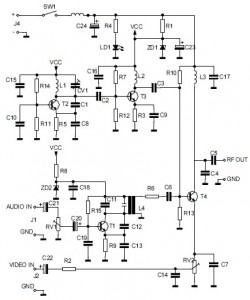
This is the circuit diagram of an audio/video modulator. The circuit converts audio and video signals into a UHF TV signal, allowing a video signal from a camera or other source to be connected to a standard TV set....
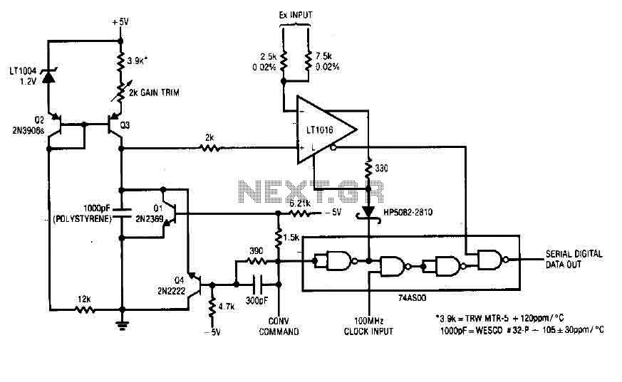
Each time a pulse is applied to the control input for conversion, Q1 resets the 1000 pF capacitor to 0 V. This resetting action takes 200 ns, after which the capacitor begins to charge linearly. In precisely 10 microseconds,...
This inverter circuit can provide up to 800mA of 12V power from a 6V supply. For example, you could run 12V car accessories in a 6V (British?) car. The circuit is simple, about 75% efficient and quite useful. By...
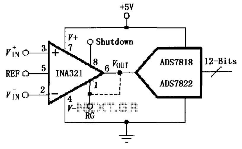
The INA321/322 is configured to directly drive the capacitive input of an A/D converter. Due to its low output resistance, the INA321/322 can effectively handle high frequency signals and directly drive capacitive loads. The input voltage is amplified by...
This circuit diagram illustrates the conversion of a speaker into a microphone. When sound waves impact the diaphragm of a speaker, fluctuations occur in the coil, generating an induced voltage. This induced voltage is typically substantial but low in...
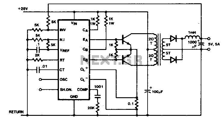
Push-pull outputs are utilized in this transformer-coupled DC-DC regulating converter. It is important to note that the oscillator must be configured to operate at twice the desired output frequency, as the SGI 524's internal flip-flop divides the frequency by...