
DC-DC regulating converter
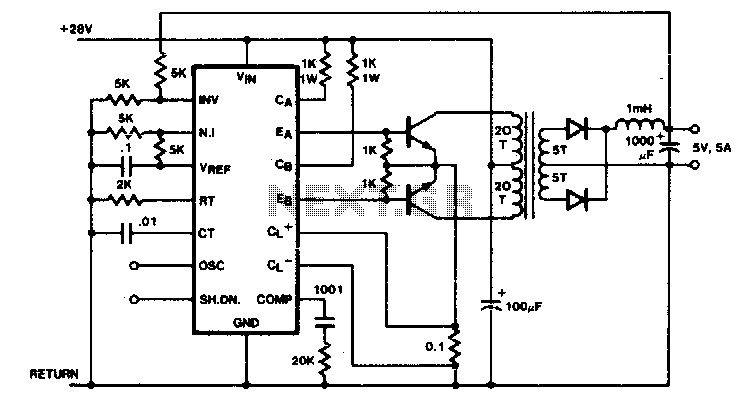
In this transformer-coupled DC-DC regulating converter, the push-pull topology is employed to effectively manage power conversion and regulation. The configuration utilizes two transistors that alternately switch on and off, allowing for efficient energy transfer from the primary winding of the transformer to the secondary winding. The SGI 524 integrated circuit plays a critical role in this design by generating the necessary PWM (Pulse Width Modulation) control signals. The oscillator frequency must be set to twice the target output frequency to compensate for the internal frequency division performed by the flip-flop within the SGI 524. This ensures that the output frequency remains stable and adheres to the design specifications.
Additionally, the current limiting feature is crucial for protecting the circuit from potential damage due to transformer saturation. In the primary side of the converter, a current sensing mechanism monitors the flow of current through the transformer. When the current exceeds a predefined threshold, the pulse width of the PWM signal is automatically reduced. This action limits the energy delivered to the transformer, preventing saturation and ensuring that the system operates within safe parameters. The combination of push-pull outputs, precise frequency control, and current limiting mechanisms contributes to the overall reliability and efficiency of the DC-DC converter circuit.Push-pull outputs are used in this transformer-coupled dc-dc regulating converter. Note that the oscillator must be set at twice the desired output frequency as the SGI 524"s internal flip-flop divides the frequency by 2 as it switches the PWM signal from one output to the other Current limiting is done here in the primary so that the pulse width will be reduced should transformer saturation occur. 🔗 External reference
Related Circuits
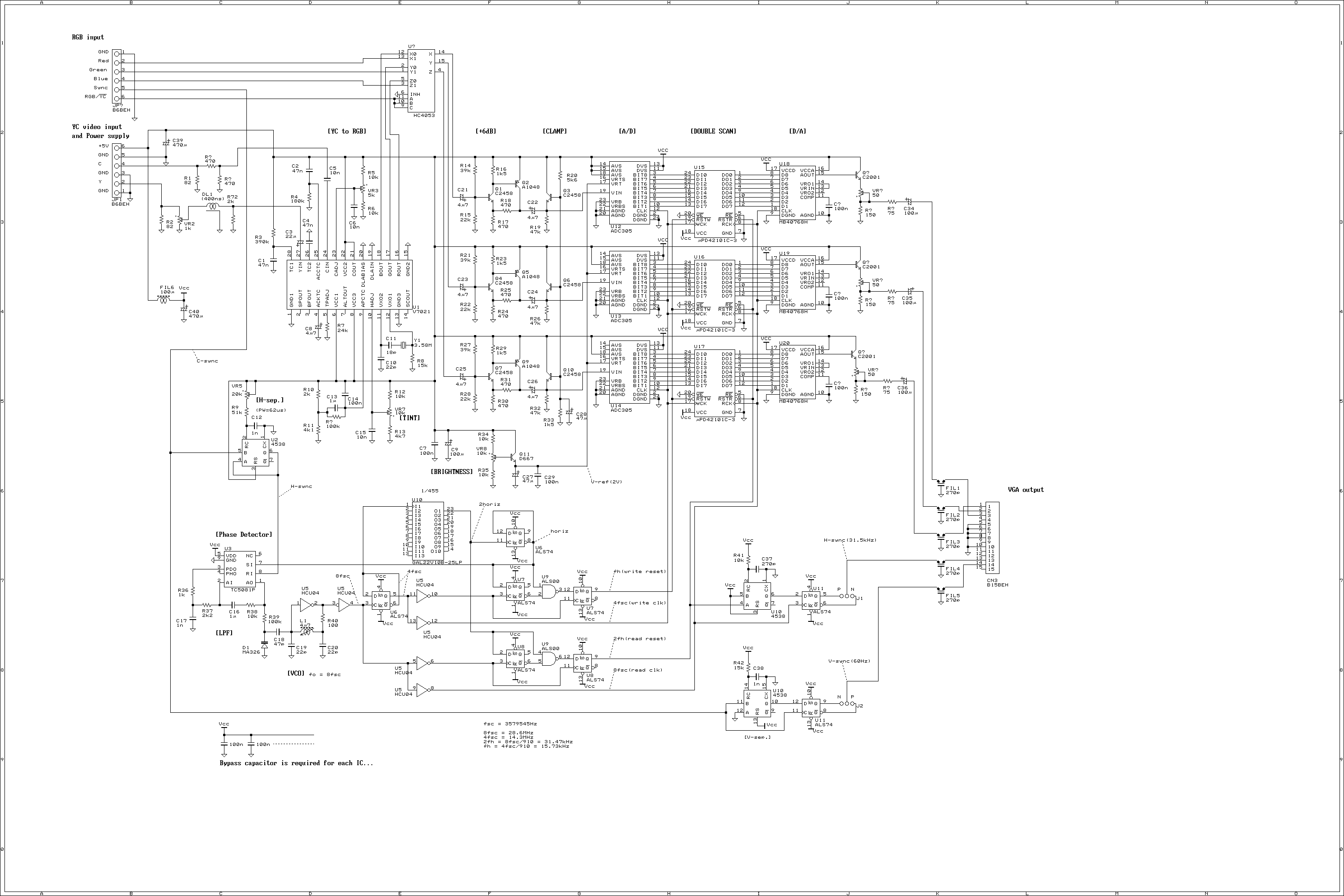
This is a video scan converter to display NTSC video signal into VGA monitor. Normally, the VGA monitor occupies most desk top space, so that everybody will be thinking that if the VGA monitor can be used for video...
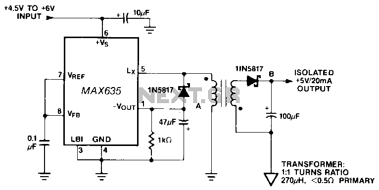
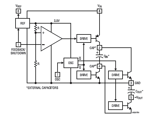
In this circuit, a negative output voltage DC-DC converter generates a -5 V output at pin A. To achieve -5 V at point A, the primary of the transformer must fly back to a diode drop that is more...
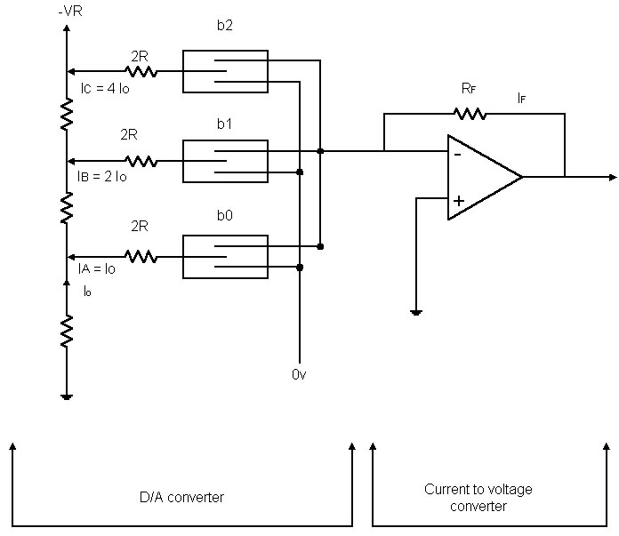
Before examining the various analog-to-digital (A-D) and digital-to-analog (D-A) conversion processes, it is useful to review the properties of each type of representation; in particular, this may help select the representation most suited to the problem at hand. An...
Chapter 4, part five of a five-part series titled "Some Thoughts on DC/DC Converters," authored by the late Jim Williams and Brian Huffman, is included in Volume II of the book "Analog Circuit Design-- Immersion in the Black Art...
This circuit was designed to provide a 5 V output from a 24 V battery of a solar-powered generator. While solar power is essentially free, it is crucial to avoid waste, especially in small installations; if the battery depletes...
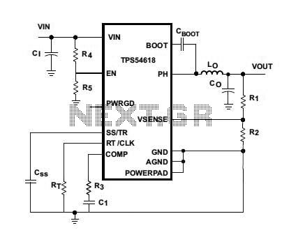
Texas Instruments introduced the TPS54618, a 6-A step-down SWIFT DC/DC converter. The new TPS54618 is a monolithic synchronous switcher featuring two integrated 12-milliohm MOSFETs. The TPS54618 is designed to provide high efficiency and compact solutions for powering a variety of...
Warning: include(partials/cookie-banner.php): Failed to open stream: Permission denied in /var/www/html/nextgr/view-circuit.php on line 713
Warning: include(): Failed opening 'partials/cookie-banner.php' for inclusion (include_path='.:/usr/share/php') in /var/www/html/nextgr/view-circuit.php on line 713